Before removing the idler rod, leave the gearbox mechanism in neutral, so that the rod is free.
To remove it, separate the selector cable fastener so that the cable is not damaged.
Plastic idler rod:
l
Cable end-piece must be detached from gate selector cable before removing relay lever.
This will avoid damage to the gate selector cable.
–
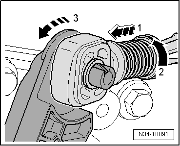
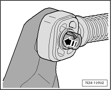
Pull locking mechanism forwards in direction of -arrow 1- onto stop and then turn to left in direction of -arrow 2- to lock.
–
Then press the idler rod forwards, towards -arrow 3-.
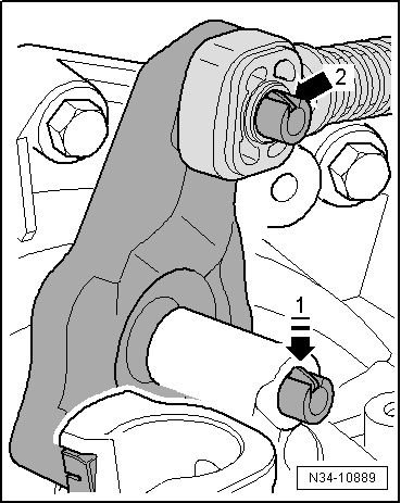
Relay lever with catch -arrow 1- (⇒ previous figure)
–
Press catch -arrow 1- (⇒ previous figure) down to stop and remove relay lever together with cable end-piece. Move relay lever in normal direction of operation.
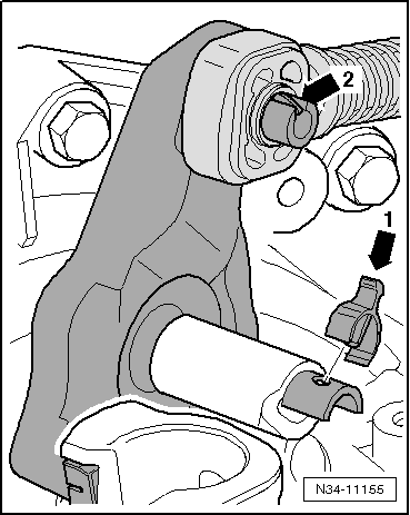
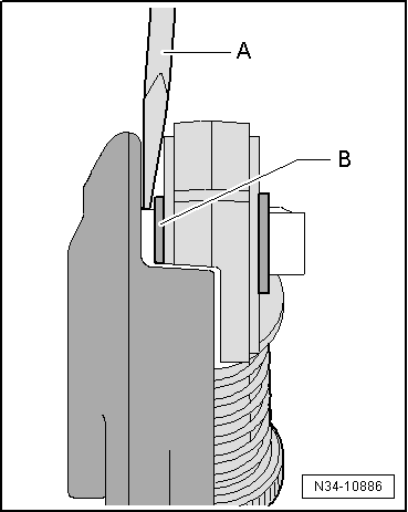
Relay lever with clip -arrow 1-
–
Remove the clip -arrow 1- and remove the relay lever together with the fixing elements of the cable.
Continued for all vehicles
Cable end-piece must be behind detent -arrow 2-.
l
The cable end-piece can only be detached with the relay lever removed → Fig.
l
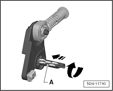
When installing, grease following areas particularly carefully.
l
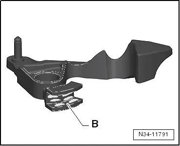
Shaft -A- of relay lever -arrows-.
l
Guide rail -B- of gearbox selector lever in which relay lever engages.
l
The original relay lever and the gearbox selector lever may vary from that shown in the figure.
 WARNING