seat Workshop Repair Guides

SEAT Workshop Service and Repair Manuals

Gearbox housing > < Removing
Installing
Installing
l  A new deep groove ball bearing has been pressed onto the input shaft ⇒ Assembly overview - input shaft → Item.
   
Turbo diesel engine gearbox
  N34-10943
–  Secure the support bridge -T10323- as shown.
–  Set input shaft in clutch housing together with selector rod for 5th and 6th gears.
Lift input shaft -1- by rotating the support bridge -T10323- spindle until it reaches the-a- dimension.
l  Dimension -a- = 15 mm
  N34-10464
–  Secure left stub shaft -A- to differential so that differential can be raised during the following steps.
–  Install differential.
A second mechanic is required for the next steps.
–  Lift differential in -direction of arrow- (2nd mechanic).
–  First set output shaft for 1st and 2nd gears -1- together with selector rod -2- in bearing seat and then swing to input shaft -3-.
  N34-10963
–  Lift input shaft for 1st and 2nd gears at synchromeshed gear -arrow A- and swing to input shaft (2nd mechanic).
–  Guide reverse gear output shaft -1- under teeth of synchromeshed gear -arrow A- and then set in bearing seat -arrow B-.
Turn the support bridge -T10323- so as to lower the input shaft by approx. 10 mm.
  N34-10466
Installation position of selector rod for 3rd and 4th gears (no. -1-)
Shorter arm -arrow- faces clutch housing.
–  Insert output shaft for 3rd and 4th gear -2- together with selector rod for 3rd and 4th gear -1-.
–  Detach left flange shaft -3- from differential.
  N34-10467
–  Lower the input shaft-A- using the support bridge -T10323- spindle, until it is slightly loaded (approx. 1 mm raised).
  N34-10945
–  Set reverse gear selector fork -A- in locking collar of reverse gear output shaft.
l  Studs -arrows- must be vertical before gearbox housing is set in place.
  N34-10468
l  Deep groove ball bearing of input shaft fits into gearbox housing in only one position.
l  Flats -A- on deep groove ball bearing and on bearing support -B- in gearbox housing must line up.
–  Mark the flattened area in colour.
–  Transfer markings to upper area of deep groove ball bearing and to upper area of bearing support of gearbox housing (⇒ next figure).
–  Heat the gearbox housing e.g. using hot air blower -VAG 1416- in area round bearing seats for grooved ball bearing/input shaft for approx. 10 minutes long to 100 °C.
  Note
Heating is necessary to avoid damage to deep groove ball bearing when gearbox housing is installed.
–  Apply sealant -AMV 188 200 03- evenly to sealing surface of clutch housing.
  N34-10967
–  Line up marking on deep groove ball bearing -A- with marking on gearbox housing -B- and set gearbox housing in place.
–  Observe studs for reverse gear selector fork. → Anchor
l  Do not cant gearbox housing when setting it in place. Guide parallel to clutch housing.
  N34-10968
–  Install retaining ring -1- for deep groove ball bearing of input shaft.
  N34-10469
–  Remove support bridge -T10323- for the input shaft -A-.
  N34-10945
–  Bolt gearbox housing and clutch housing together and tighten to specified torque.
l  Note different bolts and specified torques → Item
  Note
If bolts -B- were removed, install them now.
–  Insert stub shaft -A- together with compression spring, thrust washer and tapered ring.
–  Unscrew securing bolts from the stub shaft. To do this the stub shaft must be locked using the counterhold -T10371-.
Gearbox for front-wheel drive
–  Insert right stub shaft together with compression spring, thrust washer and tapered ring.
–  Unscrew securing bolts from the stub shaft. To do this the stub shaft must be locked using the counterhold -T10371-.
Continuation for all vehicles
Install selector unit as follows:
–  Turn gearbox in repair stand with opening for selector unit upwards.
–  Move selector rods to neutral.
  N34-10938
–  Guide selector unit with selector finger -1- through gear selector forks -A- and -B- (gear selector forks ⇒ next figure).
  N34-10958
Gear selector fork -A- and -B-
–  Turn selector unit in -direction of arrow- (⇒ previous figure) until it can be guided into gearbox housing.
  N34-10959
–  Then turn selector unit in -direction of arrow- until selector finger -2- points in indicated position.
–  Insert selector unit with selector finger into gear selector forks -A- and -B- (⇒ previous figure) and, at same time, insert into gearbox housing to stop.
l  The gear selection shaft must move easily in both directions (movement for selecting the gate).
  N34-10960
–  Tighten selector unit -B-.
–  Screw in reversing light switch -F4--A-.
–  Tighten hexagon nuts -C-.
–  Gearboxes for vehicles with start-stop system: install gearbox neutral position sender -G701--arrow- and tighten the bolt to the corresponding tightening torque → Item.
  N34-11706
–  If present, install tachograph sender -G75--A--arrow-.
–  Drive in new input shaft oil seal → Chapter.
–  Install slave cylinder with release bearing → Chapter.
–  Tighten the countersunk bolt for the stub shaft on the right using the hexagon socket -T10107A-; to do this the stub shaft must be locked using the counterhold -T10371-.
–  Shift through all gears.
  N34-10485
–  Drive cover plate into gearbox housing to stop of thrust piece -T10042-.
  N34-10472
Securing sealing cover:
Threaded holes -arrows- near sealing cover:
–  Secure locking plate -1- with 3 bolts.
  N34-11066
No threaded holes arrows near sealing cover:
–  Attach securing clip -2- with a centre hex stud -1-.
Installation position:
l  The retaining clip must be positioned over the centre of the sealing cover.
Allocate bolts and other components using → Electronic parts catalogue „ETKA“.
  N34-11065
Gearbox for all-wheel drive in conjunction with turbo diesel engine
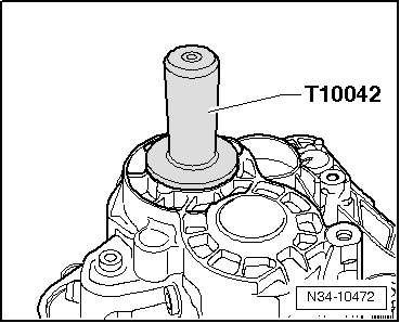
Mount bevel box on manual gearbox outside vehicle.
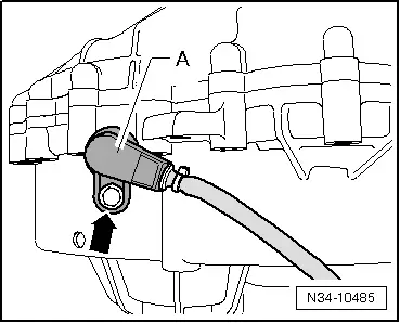
–  Grease splines of differential with grease for clutch plate splines -G 000 100-.
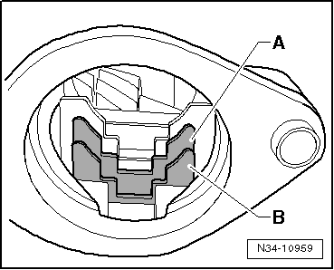
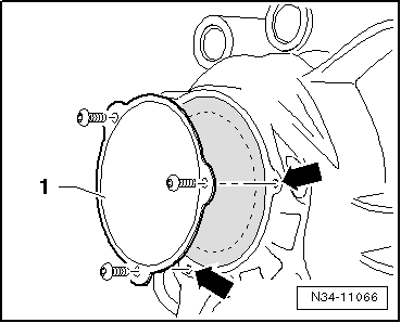
–  Push bevel box completely onto gearbox, ensuring that splines of bevel box input shaft and differential are centred when brought together.
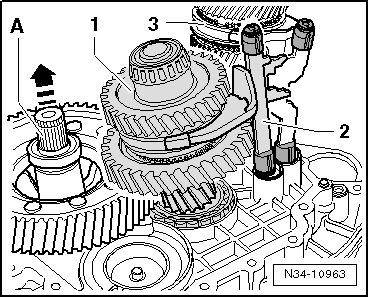
–  Align splines of right stub shaft and differential bevel gear, turning stub shaft if necessary.
–  If splines are correctly positioned and shafts are centred, then bevel box will slide to stop against gearbox.
  Note
Do not use securing bolts to pull bevel box onto gearbox, or bevel box will cant and bolt holes can break off.
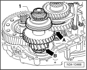
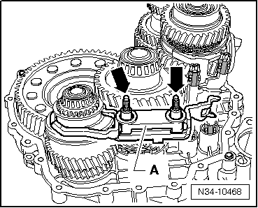
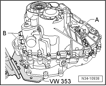
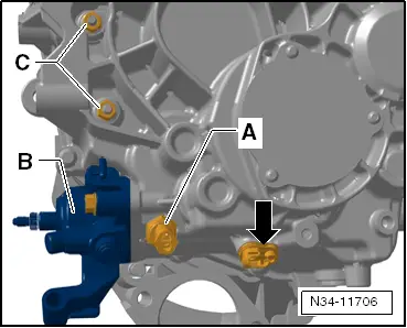
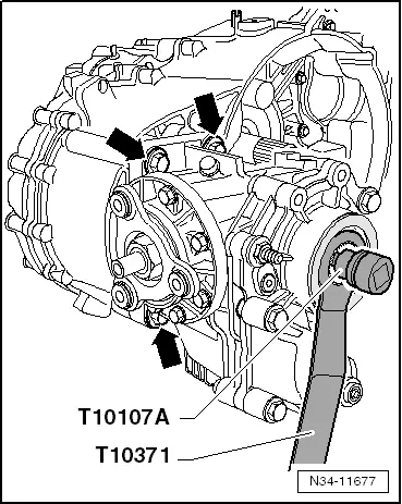
–  Tighten the 4 connecting bolts -arrows- for bevel box to gearbox with specified torque (only 3 are visible in figure) → Item.
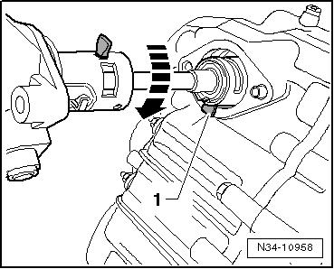
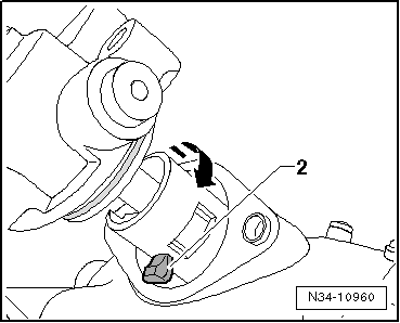
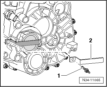
–  Tighten the countersunk bolt for the stub shaft on the right using the hexagon socket -T10107A- to the corresponding tightening torque → Item.
  N34-11677

Gearbox housing > < Removing