
Leon Mk2
| Dismantling and assembling output shaft for 1st and 2nd gear |
| Special tools and workshop equipment required |
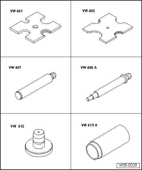
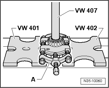
| t | Pressure plate -VW 401- |
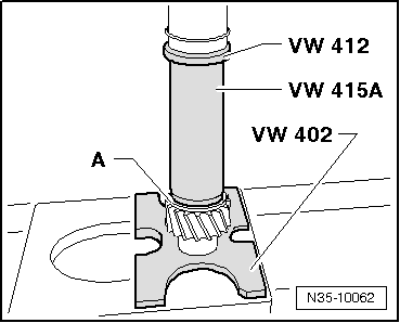
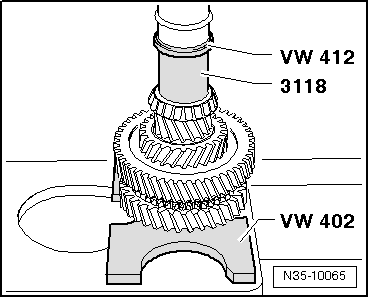
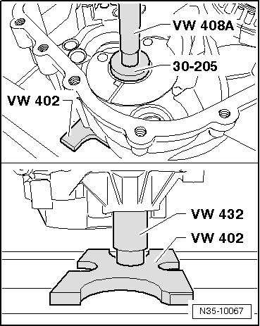
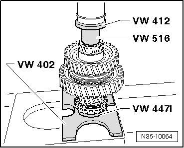
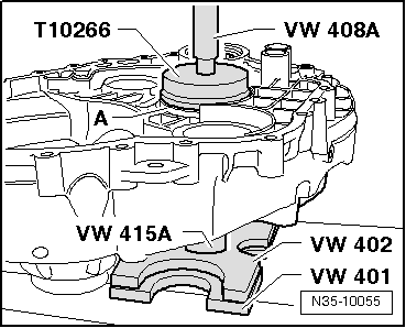
| t | Pressure plate -VW 402- |
| t | Press die. -VW 407- |
| t | Press die. -VW 408 A- |
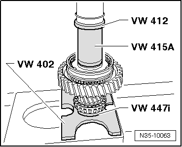
| t | Press die. -VW 412- |
| t | Tube -VW 415 A- |
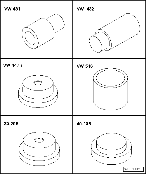
| t | Thrust piece -VW 431- |
| t | Thrust piece -VW 432- |
| t | Thrust pad -VW 447 i- |
| t | Tube -VW 516- |
| t | Tightening plate -30 - 205- |
| t | Tightening plate -40 - 105- |
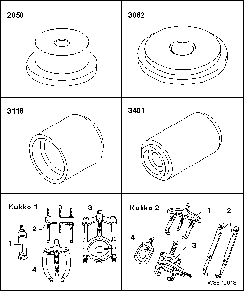
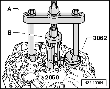
| t | Thrust piece -2050- |
| t | Thrust pad -3062- |
| t | Thrust piece -3118- |
| t | Thrust piece -3401- |
| t | -1-Internal puller 14.5...18.5 mm, e.g. -Kukko 21/2- |
| t | -1-Internal puller 46...58 mm, e.g. -Kukko 21/7- |
| t | -1-Internal puller 56...110 mm, e.g. -Kukko 21/89- |
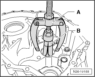
| t | -3-Splitter, 22 ... 115 mm, e.g. -Kukko 17/2- |
| t | -4-Counter support , e.g. -Kukko 22/1- |
| t | -4-Counter support , e.g. -Kukko 22/2- |
| t | -4-Counter support , e.g. -Kukko 22/4- |
| t | -1-Two arm puller, e.g. -Kukko 20/10- |
| t | Feeler gauge |
|
|
|
|
|
|
|
|
 Note
Note
|
|
|
|
|
|
|
|
|
|
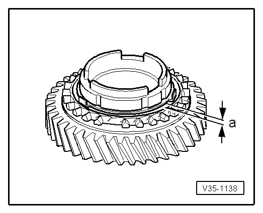
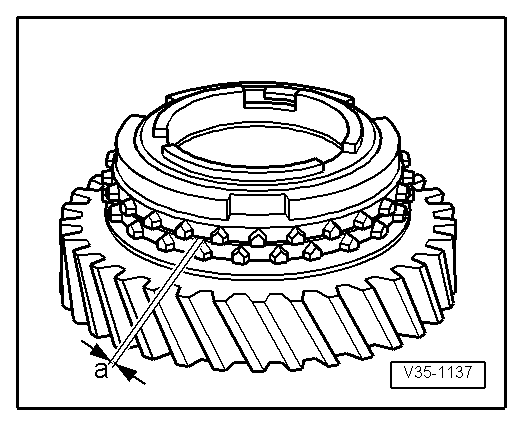
| Dimension -a- | Installation dimension | Wear limit |
| 1. and 2nd gear | 0.75 … 1.25 mm | 0.3 mm |
|
|
| Dimension -a- | Installation dimension | Wear limit |
| 1. and 2nd gear | 1.0 … 1.8 mm | 0.5 mm |
|
|
|
|
|
|
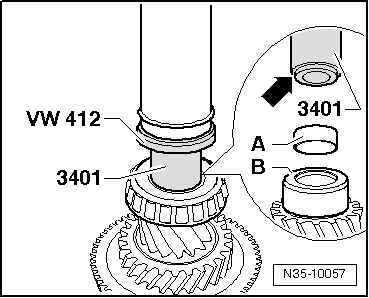
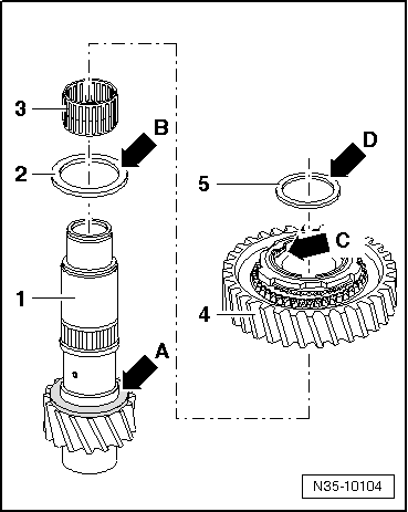
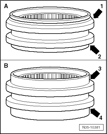
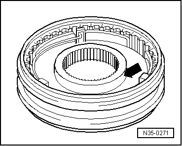
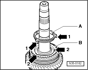
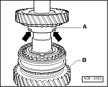
| -A- | ||
| Chamfer -arrow 1- faces lower shoulder of synchro-hub. | ||
| Shoulder -arrow 2- faces higher shoulder of synchro-hub. |
| -B- | ||
| Shoulder -arrow 3- and shoulder -arrow 4- are the same size = no installation position. |
|
|
|
|
|
|
|
|
|
|
|
Note
|
|
|
|
|
|
|
|
|
|
Note
|
|
|
|