
Leon Mk2
|

| Special tools and workshop equipment required |
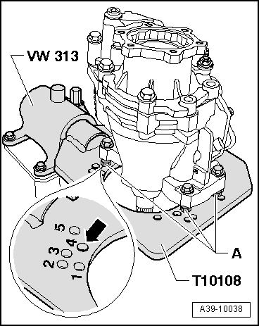
| t | Clamping frame -VW 313- |
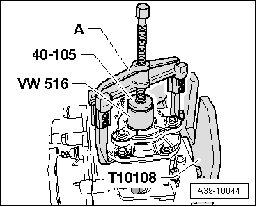
| t | Tube element -VW 516- |
| t | Thrust pad -40-105- |
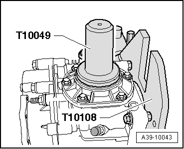
| t | Thrust blocks -T10049- |
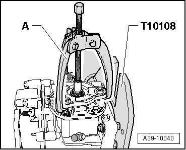
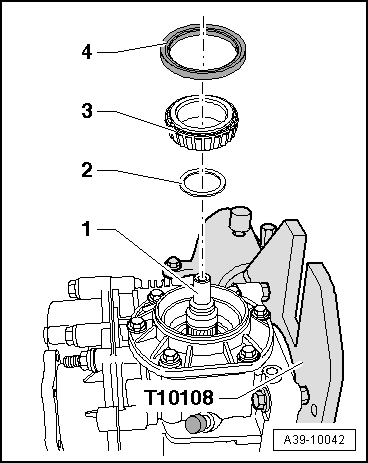
| t | Gearbox support -T10108- |
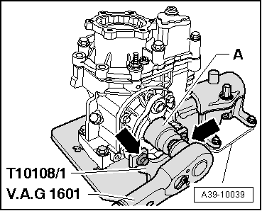
| t | Gearbox support -T10108/1- |

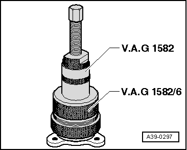
| t | Roller bearing bush extractor -V.A.G 1582- |
| t | Adapter -V.A.G 1582/6A- |
| t | Torque wrench -V.A.G 1601- |
| t | -1-Extractor 2p -KUKKO 20/10 - and Extractor 3p -KUKKO 45/2- |

| t | Extractor -SAT 1100-, see equivalent → Anchor |
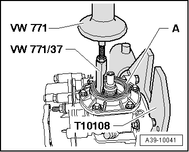
| t | Multipurpose tool -VW 771- |
| t | Pulling device -VW 771/37- |
| t | Sealing grease -G 052 128 A1- |
| t | 4 bolts M10 x 30 + 4 nuts M10 |
| t | 4 nuts M12 x 10 |
 Note
Note
|
|
|
|
|
Note
|
|
Note
|
|
|
|
|
|
|
|
|
|
|
|