
Leon Mk2
| Electric/electronic components and locations for ABS ITT Mark 20 GI/IE |
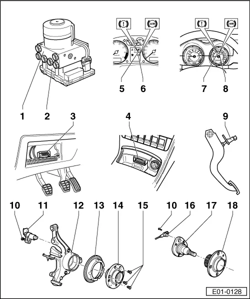
| 1 - | Hyraulic unit for ABS -N55- |
| q | Fitting location: in engine well, left-hand side |
| q | The hydraulic unit, the hydraulic pump -V64- and the inlet and outlet valves are checked by auto-diagnosis |
| q | The hydraulic pump -V64- should not be separated from the body of valves |
| q | Removing and installing → Chapter |
| q | On changing the hydraulic unit, the old part must always be closed with the cap from the repair kit part number -1H0 698 311 A- |
| 2 - | ABS control unit -J104- |
| q | Fitting location: coupled to hydraulic unit on left-hand side of engine well |
| q | Checked by self-diagnosis |
| q | Checking control unit multiple conector: → VAS 5051 |
| q | Do not uncouple connector until auto-diagnosis has been carried out. Disconnect ignition before uncoupling connector |
| 3 - | Connector for diagnosis |
| q | Fitting location: Behind fuse box cover (vehicles ► 08.00) |
| 4 - | Connector for diagnosis |
| q | Fitting location: in central consol, below ashtray (vehicles 09.00 ►) |
| 5 - | Brake system warning lamp -K118- |
| q | Fitting location: on dash panel insert (vehicles ► 08.00) |
| Function → Chapter |
| 6 - | ABS warning lamp -K47- |
| q | Fitting location: on dash panel insert (vehicles ► 08.00) |
| Function → Chapter |
| 7 - | Brake system warning lamp -K118- |
| q | Fitting location: on dash panel insert (vehicles 09.00 ►) |
| Function → Chapter |
| 8 - | ABS warning lamp -K47- |
| q | Fitting location: on dash panel insert (vehicles 09.00 ►) |
| Function → Chapter |
| 9 - | Brake switch -F- |
| q | In rest position, the brake switch is open |
| q | It can be checked in the measured value block 003: → VAS 5051 |
| q | removal and installation → Chapter |
| 10 - | Socket head bolt |
| q | 8 Nm |
| 11 - | Front left and right rev. sensors -G45-/-G47- |
| q | Checked by self-diagnosis |
| q | Before fitting the sensor, clean the interior surface of its housing and cover it with lubricating paste G 000 650 |
| q | On fitting rev. sensors, assure that the cables are not twisted when placing in them in the wheel housing |
| q | The front rotors and rev. sensors on both sides are common parts |
| 12 - | Wheel bearing housing |
| 13 - | Rev. sensorrotor |
| q | The front rotors and rev. sensors on both sides are common parts |
| q | Removing and installing: → Running gear, axles, steering; Rep. Gr.40 |
| 14 - | Wheel hub |
| q | Removing and installing: → Running gear, axles, steering; Rep. Gr.40 |
| 15 - | Cross-head screws |
| q | 4 Nm |
| 16 - | Rear left and right rev. sensors -G44-/-G46- |
| q | Checked by self-diagnosis |
| q | Before fitting the sensor, clean the interior surface of its housing and cover it with lubricating paste G 000 650 |
| q | On fitting rev. sensors, assure that the cables are not twisted when placing in them in the wheel housing |
| q | The rear rotors and rev. sensors on both sides are common parts |
| 17 - | Axle journal |
| 18 - | Wheel hub with rotor for rev. sensors |
| q | The rear rotors and rev. sensors on both sides are common parts |
| q | Removing and installing: → Running gear, axles, steering; Rep. Gr.42 |