skoda Workshop Repair Guides

Skoda Workshop Service and Repair Manuals

Testing Intake manifold temperature sender G42/G72 > < Testing components and functions
Testing Intake manifold pressure senderG71
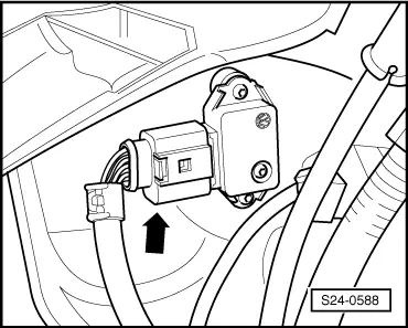
Testing Intake manifold pressure sender -G71-
  Note
Only use gilded contacts to repair contacts in the plug connection of the sender.
Special tools and workshop equipment required
t  Vehicle system tester -V.A.G 1552 - with cable -V.A.G 1551/3, 3A, 3B, 3C-
t  Test box -V.A.G 1598/31- or -V.A.G 1598/22-
t  Handheld multimeter, e.g. -V.A.G 1526 B-
t  Measuring tool set, e.g. -V.A.G 1594 C-
t  Current flow diagram
Test sequence
–  Connect vehicle system tester -V.A.G 1552-. Start engine and select address word 01 “Engine electronics” → Chapter.
–  Select function 08 “Read measured value block” and display group number 003.
   
–  Read off intake manifold pressure values indicated in display field 2.
Specified value: 240…420 mbar.
–  Briefly open throttle valve. The intake manifold pressure value in display field 2 must increase briefly.
If 91 mbar or 1254 mbar is always indicated:
 
Reading measured value block 3     ->
 770 rpm    365mbar       11%         2°
DisplayCauseContinue test
91 mbarLine interruption or short-circuit to earth → Anchor
1254 mbarShort circuit to positive → Anchor

Continuation of the test if the display reads 91 mbar:
   
–  Disconnect the 4-pin plug connection from the intake manifold pressure sender -G71- with intake manifold temperature sender -G42/G72--arrow- (engine may stall).
  S24-0588
–  Bridge contacts 3 + 4 of the plug connection and observe the read-out on the display.
If the display jumps to 1254 mbar:
–  Select function 06 “End output” and switch ignition off.
–  Replace intake manifold pressure sender -G71- with intake manifold temperature sender -G42/G72- → Chapter.
If the display remains at 91 mbar:
–  Select function 06 “End output” and switch ignition off.
–  Connect test box - V.A.G 1598/31- or -V.A.G 1598/22 - to the wiring loom of the control unit → Chapter. The engine control unit is not connected here.
  S24-0589
–  Check wiring between the test box and the 4-pin plug for interruption according to the current flow diagram → Current flow diagrams and Fitting locations
Cable resistance: max. 1.5 Ω
–  Also test wire contact 4 for short-circuit to earth and to contact 1.
Specified value: ∞ Ω
If the lines are not found to be faulty:
–  Replace engine control unit → Chapter.
Continuation of the test if the display reads 1254 mbar:
  S24-0581
–  Disconnect the 4-pin plug connection from the intake manifold pressure sender -G71- with intake manifold temperature sender -G42/G72--arrow- (engine may stall).
If the display jumps to 91 mbar:
–  Select function 06 “End output” and switch ignition off.
–  Replace intake manifold pressure sender -G71- with intake manifold temperature sender -G42/G72- → Chapter.
If the display remains at 1254 mbar:
–  Select function 06 “End output” and switch ignition off.
–  Unlock connector at control unit and unplug.
  S24-0588
–  Check the wires for plug of control unit at 4-pin plug contact 4 for short-circuit to wire contact 3 as well as after positive battery.
Specified value: ∞ Ω
If the lines are not found to be faulty:
–  Replace engine control unit → Chapter.
  S24-0581

Testing Intake manifold temperature sender G42/G72 > < Testing components and functions