
Fabia Mk1
| Repairing the air conditioning system - engine compartment |
 WARNING
|
 Note
Note| t | If the earth strap of the battery was disconnected, pay attention to the sequence when connecting it → Electrical System; Rep. Gr.27. |
| t | The parts marked with an * must only be repaired in specialist service centres which have suitably trained personnel and are fitted out for working on the refrigerant circuit! |
| t | Comply with the safety measures when working on vehicles with air conditioning system and when using refrigerant R134a and observe the instructions for working on the refrigerant circuit → Air conditioning system with refrigerant R134a; Rep. Gr.00 technical data. |
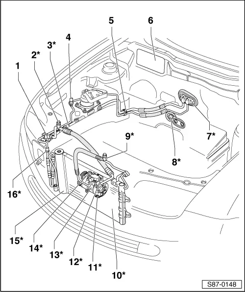
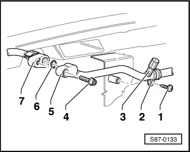
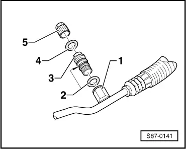
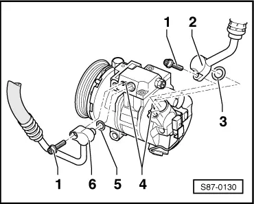
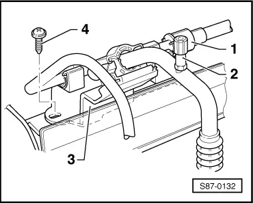
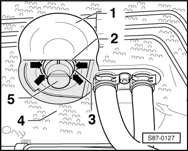
| 1 - | Holder for refrigerant lines |
| q | → Fig. |
| q | Properly secure the refrigerant lines |
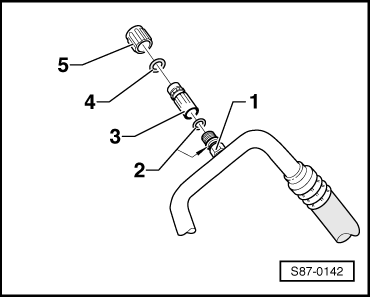
| 2 - | Exhaust valve* |
| q | Low-pressure side |
| q | for exhaust and measurement only |
| q | always screw on cap with gasket |
| q | removing and installing → Fig. |
| 3 - | Quick coupling for refrigerant line* |
| q | Low-pressure side |
| q | separate → Chapter |
| 4 - | High-pressure sender -G65- |
| q | function → Chapter |
| q | remove and install, test → Chapter |
| 5 - | Holder for refrigerant lines |
| q | bolted with plastic nut (2.7 Nm) |
| 6 - | Opening for air inlet of air conditioning unit |
| q | under cover in the cooling-water tank |
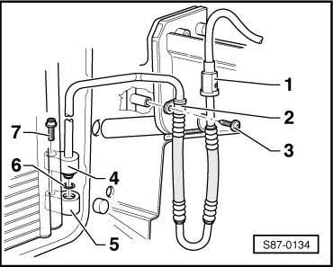
| 7 - | Expansion valve* |
| q | Removing and installing the refrigerant lines → Fig. |
| q | removing and installing → Chapter |
| 8 - | Valve for condensation water drain* |
| q | behind heat-protection matting of the bulkhead (assembly plate) |
| q | Fit only on removed air conditioning unit |
| q | check → Fig. |
| 9 - | Extractor and filling valve* |
| q | High-pressure side |
| q | for exhausting, filling and measuring |
| q | always screw on cap with gasket |
| q | removing and installing → Fig. |
| 10 - | Condenser* |
| q | Removing and installing the refrigerant lines → Fig. and → Fig. |
| q | Removing and installing the condenser → Chapter |
| 11 - | Regulating valve for compressor, air conditioning system -N280-* |
| q | Elements of the compressor, do not replace individually |
| q | check → Chapter |
| q | Coil resistor-regulating valve at 20 °C: 10.6 ± 0.4 Ω |
Note| Depending on the required cooling output the regulating valve receives a PWM signal (500 Hz) (modulated by signal interval) from the air conditioning system control unit -J301- and regulates the displacement of the compressor via the position of the articulated disc. |
| 12 - | Pressure relief valve* |
| q | O-Ring: 8.6 mm; 1.8 mm |
| q | Tightening torque: 10 Nm |
| q | function → Chapter |
| q | check → Chapter |
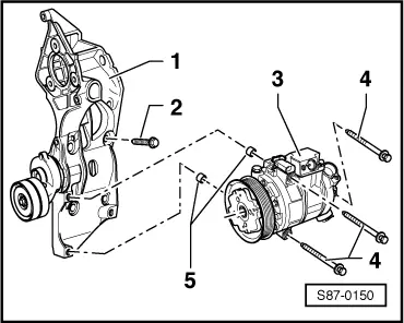
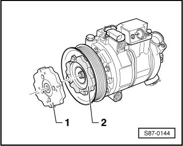
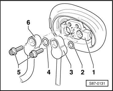
| 13 - | Compressor* |
| q | Manufacturer: Denso, designation: 6 SEU 12C |
| q | Removing and installing the compressor on the holder → Fig. |
| q | Removing and installing the refrigerant lines → Fig. |
| q | Belt protection for blocked compressor → Fig. |
| q | Removing and installing the compressor → Chapter |
| q | Running-in instruction → Chapter |
Note| t | The compressor displacement is regulated on the suction side via the externally clock-pulsed regulating valve in accordance with the required cooling output. |
| t | If the air conditioning system is switched off due to a loss of refrigerant, the lubrication of the compressor is ensured. |
| t | Do not start engine if the refrigerant lines are not connected to the compressor and the compressor is closed with plugs (risk of overheating). |
| 14 - | Oil drain plug* |
| q | with gasket |
| q | Tightening torque for: |
| M 8 - 30 Nm |
| M 10 - 40 Nm |
| To drain off refrigerant oil: |
| – | Remove compressor |
| – | Remove oil drain plug |
| – | Turn the compressor over the belt pulley to speed up drainage of the oil. |
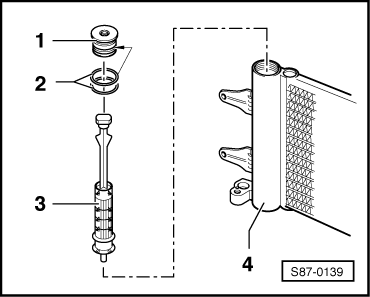
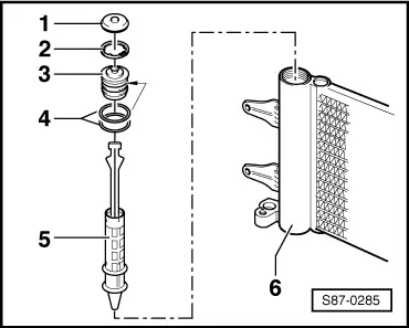
| 15 - | Fluid container with dessicator insert* |
| q | Element of the condenser |
| q | Replace dessicator insert after each opening of the refrigerant circuit → electronic catalogue of original parts |
| q | Summary of components of the dessicator insert → Fig. |
| q | Removing and installing dessicator insert → Chapter |
| 16 - | Quick coupling for refrigerant line* |
| q | High-pressure side |
| q | separate → Chapter |
Note
|
|
Note
|
|
|
|
|
|
|
|
Note
|
|
Note
|
|
|
|
|
|
Note
|
|
Note
|
|