
Fabia Mk1
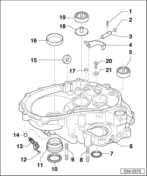
| 1 - | Tensioning sleeve |
| q | 4 x 25 mm |
| q | pull out with pliers |
| q | Install with ejector -MP 3-509- |
| 2 - | Plug |
| q | before installing apply sealant -THREE BOND 1305- |
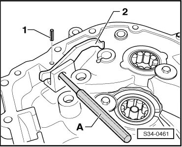
| 3 - | Bolt |
| q | for reverse gear shift fork |
| q | removing and installing → Fig. |
| 4 - | Gearshift fork reverse gear |
| q | removing and installing → Fig. |
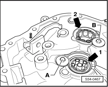
| 5 - | Cylindrical-roller bearing |
| q | for drive shaft |
| q | removing and installing → Chapter |
| q | Fitting position → Fig. |
| 6 - | Clutch housing |
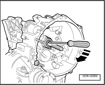
| 7 - | Gasket ring for drive shaft |
| q | removing → Fig. |
| q | inserting → Fig. |
| 8 - | Pin screw, M10 |
| 9 - | Pin screw, M10 |
| 10 - | Gasket ring |
| q | for right flange shaft |
| q | replace → Chapter |
| q | fill with sealing grease before fitting |
| q | pay attention to different versions |
| 11 - | Bushing |
| q | for gearbox after 06.00 |
| q | for right gasket ring |
| q | removing → Fig. |
| q | installing → Fig. |
| 12 - | 20 Nm |
| q | only for vehicles without ABS; from 11.02 |
| 13 - | Drive for speedometer |
| q | only for vehicles without ABS; from 11.02 |
| 14 - | O-ring |
| q | only for vehicles without ABS; from 11.02 |
| q | always replace |
| 15 - | Magnet |
| q | is held in position by the separator surface of the housing |
| 16 - | Outer ring/tapered-roller bearing |
| q | for differential |
| q | removing and installing → Chapter |
| q | when inserting: Adjusting the differential gear → Chapter |
| 17 - | Bushing for gear shift rod |
| q | removing → Fig. |
| q | inserting → Fig. |
| 18 - | Supports |
| 19 - | Cylindrical-roller bearing |
| q | for output shaft |
| q | removing and installing → Chapter |
| q | Fitting position → Fig. |
| 20 - | 10 Nm |
| 21 - | Washer |
|
|
|
|
|
|
|
|
|
|
|
|
|
|
|
|