skoda Workshop Repair Guides

Skoda Workshop Service and Repair Manuals

Securing the engine to the assembly stand > < Removing and installing engine
Removing (Roomster)
Removing (Roomster)
Special tools and workshop equipment required
t  Bushing -T30010 (VW540/1B)-
t  Adapter -MP9-200/7 (10-222A/7)-
t  Lifting device -MP9-201 (2024 A)-
t  Wire
  Note
t  The engine is removed downwards together with the gearbox.
t  All cable straps that have been loosened or cut open when the engine was removed must be attached again in the same location when the engine is installed again.
t  Collect drained coolant in a clean container for proper disposal or reuse.
   
–  Lift the engine cover at the sides -arrows A- and pull out towards the front -arrow B-.
  WARNING
Observe measures when disconnecting the battery → Electrical System; Rep. Gr.27.
–  Remove battery and battery tray → Electrical System; Rep. Gr.27.
–  Remove air filter with intake hose and hose to turbocharger → Chapter.
  S10-0374
–  Remove charge-air pipe at the top -1- with connecting hose -2--arrows-.
–  Remove the sound dampening system → Body Work; Rep. Gr.50.
–  Detach the right front wheel → Chassis; Rep. Gr.44.
–  Remove the right wheelhouse liner → Body Work; Rep. Gr.66.
  WARNING
Hot steam or hot coolant may escape when the compensation bottle is opened. Cover the cap with a cloth and open carefully.
–  Drain coolant → Chapter.
For engine with engine code AXR, BSW
  S10-0371
–  Release screw -3- and remove bottom charge air pipe -1- with connecting hose -2--arrows-.
–  Unscrew screws -arrows- for right steering joint → Chassis; Rep. Gr.40.
–  Remove charge air pipe from exhaust turbocharger to charge air cooler → Chapter.
  S10-0147
For all vehicles
  Note
After installing the screws carry out the axial measurement → Chassis; Rep. Gr.44.
–  Remove right drive shaft from the gearbox. Then swivel out drive shaft and secure below front bumper with wire, outside the engine compartment → Chassis; Rep. Gr.40.
–  Remove left drive shaft from gearbox and secure with wire → Chassis; Rep. Gr.40.
For engine with engine code AXR, BSW
–  Remove pre-exhaust pipe with catalytic converter → Chapter.
For engine with engine code BLS
–  Remove pre-exhaust pipe with diesel particle filter → Chapter.
For all vehicles
  S40-0361
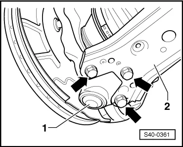
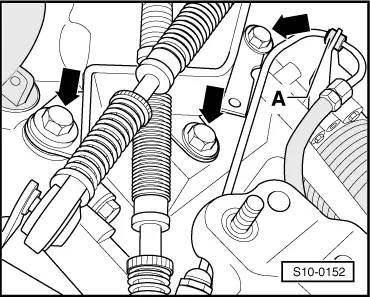
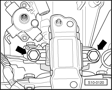
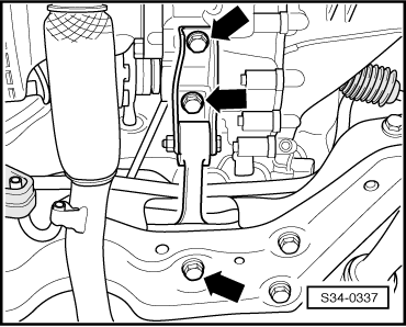
–  Unbolt the pendulum support -arrows-.
–  Remove holder for electric installation at the bottom from the gearbox.
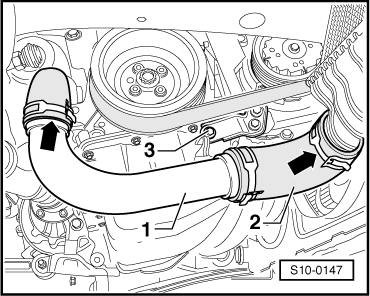
  Note
Mark the direction of rotation with chalk or a felt-tip pen before removing the V-ribbed belt. Reversing the rotation direction of an already used belt may destroy it.
–  Remove V-ribbed belt → Chapter.
–  Remove fan shroud from radiator → Chapter.
–  Remove alternator → Electrical System; Rep. Gr.27.
On vehicles with air conditioning
  WARNING
Do not open the refrigerant circuit of the air conditioning system.
  Note
In order to avoid damage to the AC compressor as well as to the refrigerant lines and hoses, ensure that the lines and hoses are not over-tensioned, kinked or bent.
–  Remove the AC compressor from the bracket for auxiliary units → Heating, Air Conditioning; Rep. Gr.87.
  S34-0337
–  Attach AC compressor -3- e.g. to radiator grill in accordance with the figure. As protection put a sheet of cardbord -1- on the radiator wall.
  Note
Avoid damage to the radiator.
Continued for all vehicles
  S10-0370
–  Disconnect the coolant hose -1- from the cylinder head.
–  Disconnect the fuel intake hose -3- and the fuel return hose -2- from the pipes.
  S10-0148
–  Remove the coolant feed hose -3- from the supports -4-.
–  Remove the coolant return hose -2- from the heat exchanger connection fittings -1-.
–  Pull off vacuum hose -6- from tandem pump -5-.
–  Unclamp all remaining connecting, coolant, vacuum and suction hoses from the engine.
–  Release all remaining plugs at engine and gearbox and lay aside the relevant lines.
  S10-0150
–  Remove Bowden cable support -arrows-.
–  Pull out slave cylinder line -A- from the holder on the gearbox.
–  Remove shift mechanism from gearbox → gearbox; Rep. Gr.34.
–  Remove the clutch slave cylinder from the gearbox → Gearbox; Rep. Gr.30.
  WARNING
After removing the slave cylinder, do not operate the clutch pedal.
  S10-0152
–  Screw engine mount -T10012- to the cylinder block with fixing nut and bolt. Tighten screw M10 x 25/8.8 to approx. 40 Nm.
–  Insert engine/gearbox jack (e.g. -V.A.G 1383 A-) into engine mount -T10012- and slightly raise.
  Note
Use double ladder (e.g. -VAS 5085-) to release the screws for the assembly bracket.
  S10-0271
–  Release the screws which connect the engine mount with the engine support -arrows-.
  S10-0149
–  Unscrew the gearbox mount from the gearbox support -arrows-.
  Note
t  Check whether all hose and line connections between engine, gearbox and body are released.
t  When lowering carefully guide the engine/gearbox jack unit, in order to avoid damage.
t  The engine and gearbox unit must be carefully guided during withdrawal. Ensure adequate clearance to other components. Particularly from the AC compressor.
–  First of all slightly lower the engine/gearbox unit. Then push engine/gearbox unit forwards to the radiator and only then lower further.
–  Remove the gearbox from the engine → gearbox; Rep. Gr.34.
  S10-0120

Securing the engine to the assembly stand > < Removing and installing engine