
Fabia Mk2
 WARNING
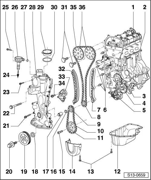
| 1 - | Cylinder head with cover |
| q | removing and installing → Chapter |
| 2 - | Cylinder block |
| q | 2 part |
| q | do not separate |
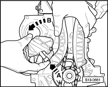
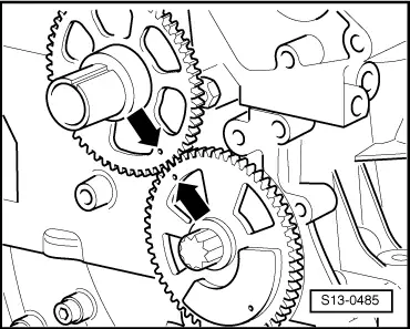
| 3 - | Balancing shaft |
| 4 - | Balancing shaft gear |
| q | do not remove |
| q | Wheel position for crankshaft gear → Fig. |
| 5 - | Oil pump |
| q | removing and installing → Chapter |
| 6 - | Bolt, 18 Nm |
| q | for tensioning rail or possibly also guide rail |
| 7 - | Guide rail |
| 8 - | Chain sprocket on the crankshaft for the camshaft drive |
| q | interlocked with spring on the crankshaft |
| 9 - | Chain sprocket on the crankshaft for the oil pump drive |
| q | not interlocked on the crankshaft |
| 10 - | Oil pump chain |
| 11 - | Oil pump sprocket |
| 12 - | Oil pan |
| q | removing and installing → Chapter |
| 13 - | 9 Nm |
| 14 - | Cover |
| q | for chain sprocket of the oil pump |
| 15 - | 20 Nm + torque a further 90° (1/4 turn) |
| q | replace |
| 16 - | O-ring |
| q | replace if damaged |
| 17 - | Housing |
| q | replace together with O-ring (Pos. 16) |
| q | fit onto cleaned crankshaft |
| q | install only after putting the timing case in place, otherwise the gasket ring can be damaged |
| 18 - | Sealing ring |
| q | replace if damaged → Chapter |
| q | replace together with housing (Pos. 17) |
| q | for crankshaft on the belt pulley side |
| q | Neither grease nor oil sealing lip of gasket ring |
| q | before installing remove grease residue on the housing with a clean cloth |
| 19 - | Belt pulley - crankshaft |
| 20 - | 150 Nm + torque a further 180° (1/4 turn) |
| q | replace |
| q | interlock the crankshaft with fixing bolt -T10121- for removing and installing → Chapter |
| 21 - | 25 Nm |
| 22 - | 50 Nm |
| 23 - | 8 Nm + torque a further 90° (1/4 turn) |
| q | if no blue sealing compound is left in the thread of the M6 screws, replace the screws for ones which have sealant on them |
| 24 - | To intake manifold |
| q | Overview of intake manifold → Chapter |
| 25 - | 10 Nm |
| 26 - | The vacuum regulating valve (PCV valve) |
| q | Pay attention to the part number |
| 27 - | O-ring |
| q | replace if damaged |
| 28 - | Timing case |
| q | removing and installing → Chapter |
| 29 - | Cover |
| 30 - | O-ring |
| q | replace if damaged |
| 31 - | 50 Nm + torque a further 90° (1/4 turn) |
| q | replace |
| q | for removing and installing, interlock camshafts with camshaft fixer/locator -T10123- → Chapter and use the counterholder -T10172- → Chapter |
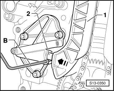
| 32 - | Tensioning rail |
| q | interlock tensioner → Fig. |
| 33 - | Hydraulic control chain tensioner |
| 34 - | 9 Nm |
| 35 - | Timing chain |
| 36 - | Camshaft sprocket |
| q | removing and installing, setting the timing → Chapter |
|
|
|
|
|
|