
Fabia Mk2
| Connection diagram for vacuum hoses |
 Caution
|
 Note
Note| t | Blue = vacuum control line for exhaust gas recirculation |
| t | Grey = ventilation line to air filter |
| t | Green = vacuum control line for exhaust gas turbocharger |
| t | Red = vacuum supply line of the vacuum pump |
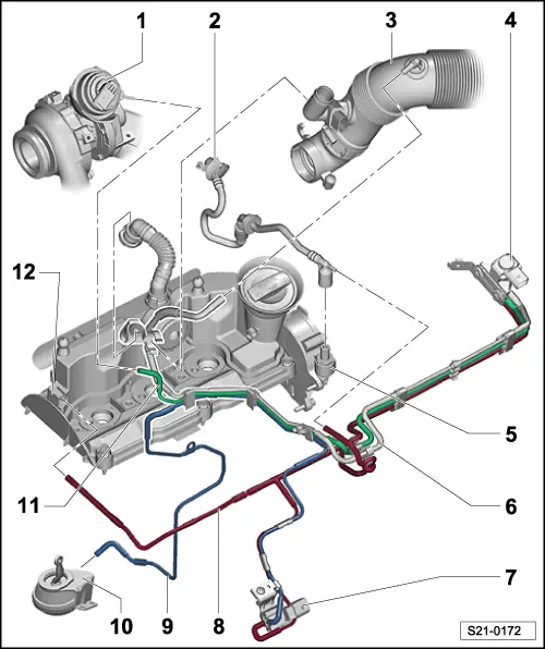
| 1 - | Vacuum setting element |
| q | at exhaust gas turbocharger |
| q | with position sender for charge pressure regulator -G581- |
| 2 - | Vacuum line |
| q | To the brake servo unit |
| 3 - | Air intake hose |
| q | with connecting piece for ventilation line |
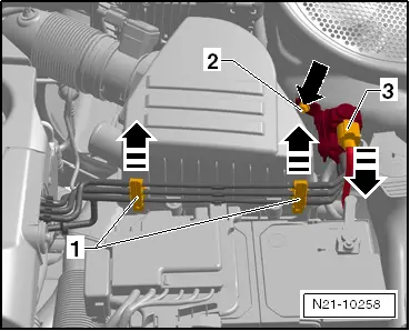
| 4 - | Solenoid valve for charge pressure control -N75- |
| q | removing → Fig. |
| 5 - | Vacuum pump |
| 6 - | Vent line |
| q | To intake hose |
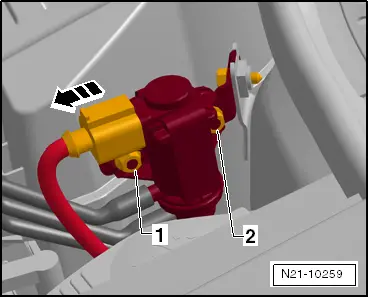
| 7 - | Changeover valve for radiator of exhaust gas recirculation -N345- |
| q | Check change-over → Chapter |
| 8 - | Vacuum line |
| q | to cylinder head cover with vacuum reservoir |
| 9 - | Vacuum line |
| q | to vacuum setting element at radiator for exhaust gas recirculation |
| 10 - | Vacuum setting element |
| q | the radiator flap for exhaust gas recirculation |
| 11 - | Vacuum line |
| q | to vacuum setting element at exhaust gas turbocharger |
| 12 - | Vacuum connection |
| q | at the cylinder head cover with vacuum reservoir |
|
|
|
|