skoda Workshop Repair Guides

Skoda Workshop Service and Repair Manuals

Replacing engine control unit > < Testing activated charcoal filter system solenoid valve 1 N80
Test fuel pump relay and control
Special tools and workshop equipment required
t  Test box -V.A.G 1598/22-
t  Hand-held multimeter e.g. -V.A.G 1526 A - or multimeter -V.A.G 1715-
t  Voltage tester, e.g. - V.A.G 1527-
t  Measuring tool set -V.A.G 1594 A -
t  Current flow diagram
Test conditions
l  The fuse 132 in fuse holder on battery must be O.K.
  Note
   
The fuel pump relay is located on the relay carrier in the interior of the vehicle behind the stowage compartment in the driver's footwell, plug location 4.
A - Test fuel pump relay -J17-
  S24-0181
–  Take fuse 28 out of the fuse holder and connect the voltage tester between earth and one of the two contacts for fuse 28 in the fuse holder.
–  Switch on the starter motor for a short time.
The fuel pump relay must close (be felt and audible); the voltage tester must light up.
–  If the voltage tester does not light up, although the fuel pump relay has been connected, repeat the test on the second contact.
  S24-0300
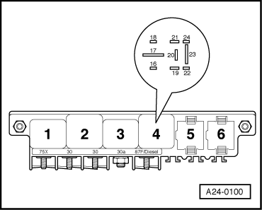
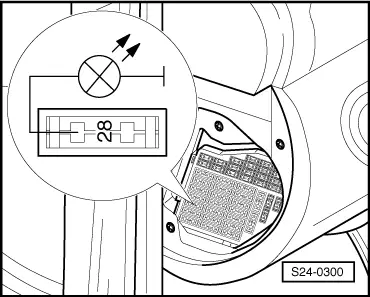
–  If the voltage tester still does not light up, test the wiring between the contact 23 (relay position 4) and the fuse 28 for continuity, if necessary eliminate the open circuit.
   → Current flow diagrams and Fitting locations
–  If no open circuit was detected, replace the fuel pump relay.
–  If the fuel pump relay does not connect, test control → Anchor.
–  If the power supply and the actuation are o.k., replace the fuel pump relay.
B - Test voltage supply and control of the fuel pump relay
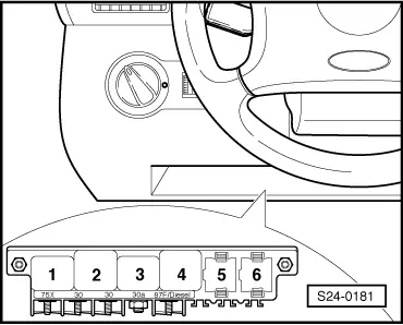
–  Pull the fuel pump relay J17 out of the relay base, relay position 4.
Checking voltage supply
  A24-0100
–  Connect hand-held multimeter for voltage measurement consecutively to contact 19 (positive) and earth as well as to 17 (positive) and earth.
–  Switch on ignition. If the engine is not switched on, the relay is activated for approx. 10 s.
Specified value: approx. battery voltage
–  If the specified values are not reached, eliminate line interruption.
   → Current flow diagrams and Fitting locations
Test control
  A24-0100
–  Connect voltage tester to contact 16 (earth) and positive.
–  The voltage tester must light up permanently after starting.
  Note
The voltage tester with low power consumption does not go out fully but remains slightly lit until the starter is operated.
If the voltage tester does not light up, test wiring as follows:
  A24-0100
–  Connect test box -V.A.G 1598/22 - at wiring loom to the engine control unit.
–  Connect hand-held multimeter between contact 16 of relay base and socket 4 of the test box and test wiring for continuity.
–  If the wiring is not interrupted and the voltage tester does not light up: replace engine control unit → Chapter.
–  If the actuation of the fuel pump relay as well as the cables are o.k.: replace the fuel pump relay.
–  Insert fuse 28.
  S24-0148

Replacing engine control unit > < Testing activated charcoal filter system solenoid valve 1 N80