skoda Workshop Repair Guides

Skoda Workshop Service and Repair Manuals

Removing and installing heat exchanger > < 2 way valve for coolant shut-off valve N147
Removing and installing heater unit
Removing
–  Removing dust and pollen filter with housing → Chapter.
–  Determine the code for radio sets fitted with anti-theft coding.
–  Disconnect battery.
–  Reduce pressure in the coolant circuit by opening the cap on the coolant expansion reservoir.
   
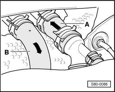
–  Disconnect both coolant hoses to heat exchanger of the heater with hose clamps (e. g. - V.A.G 3094-).
  Note
t  Connect the coolant hoses the right way round: - Coolant hose -A- Feed from the cylinder head, coolant hose -B- Return flow to the water pump.
t  Bleed the refrigerant circuit → Engine, Mechanics; Rep. Gr.19.
  S80-0086
–  Position the reservoir under the connection for the hose -B- and via the connection for the hose -A- carefully blow the coolant out of the heat exchanger (with compressed air).
  S80-0086
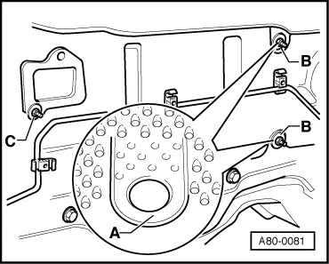
–  Slightly raise the pre-type punched points -A- of the heat protection matting and remove the hexagon nuts with washer -B- located behind them (tightening torque 15 Nm).
–  Remove hexagon nut with washer -C-.
  Note
A gasket must be present at the washers of the hexagon nuts for sealing.
–  Removing the dash panel → Body Work; Rep. Gr.70
–  Remove right footwell vent → Chapter.
–  Removing passenger-side airbag unit → Electrical System; Rep. Gr.96.
–  All opened connectors and the air guides of the heater unit must be covered to prevent any swarf from penetrating.
  A80-0081
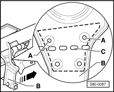
–  Bore out the support for the dash panel at the points marked (connection points) with -A- using a 7 mm drill Ø.
–  Bend part -B- to the side at the predetermined breaking point -C- in -direction of arrow-.
  Note
After installing the heater unit, bend the part -B- back in its original position and screw the molded part drawn with interrupted lines to the bores -A- (e. g. with screws M6x10).
–  Disconnect electrical connection between vehicle and heater unit (plug connection and bolted earth cable to -A- pillar.
  S80-0087
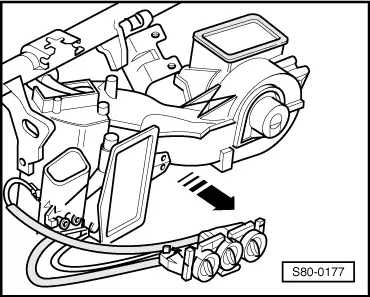
–  Remove heater unit in -direction of the arrow-.
Install
Installation is performed in the reverse order, pay attention to the following points:
  Note
t  Check all the gaskets at the heater unit for damage before installing, replace damaged gaskets.
t  Before inserting the heater unit, check the gasket at the suction channel as it must touch the body.
  S80-0177
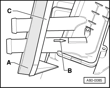
t  Replace gasket -A- at the heat exchanger and check for correct fitting at the contact surface -C-.
t  At the connection to the heat exchanger, the flow direction of the coolant is indicated (-arrow B-).
t  All the cable binders which must be removed for removing the heater unit must be fitted again at the same point after the assembly.
  A80-0085

Removing and installing heat exchanger > < 2 way valve for coolant shut-off valve N147