
Octavia Mk2
| Summary of components - Vehicles with left-hand drive |
 Note
Note| The master brake cylinder and the brake servo unit can be replaced independently of one another. |
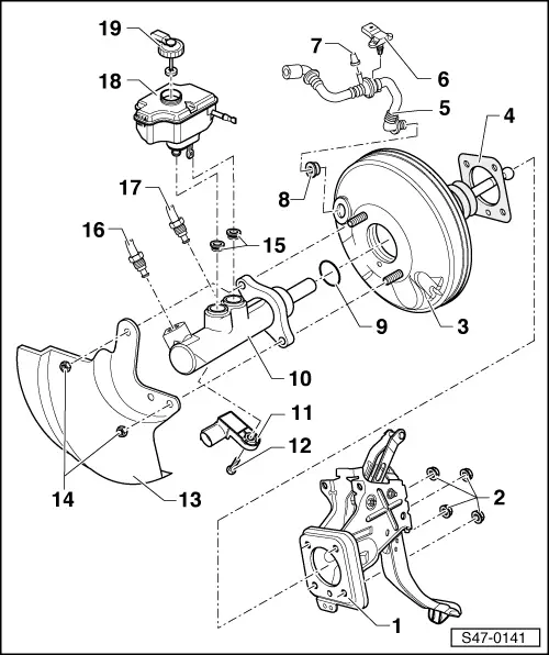
| 1 - | Foot Controls |
| q | different versions |
| q | Assignment → Electronic Catalogue of Original Parts |
| 2 - | Self-locking nut, 25 Nm |
| q | replace after each removal |
| 3 - | Brake servo unit |
| q | on petrol engines, the required negative pressure is drawn from the induction pipe or it is generated with a vacuum pump |
| q | Vehicles fitted with petrol engines and automatic gearbox are equipped with a brake vacuum pump -V192- → Chapter. |
| q | vehicles using a diesel engine are fitted with a vacuum pump for generating a low pressure → Chapter |
| q | Functional test: |
| – | With the engine off press down brake pedal repeatedly with force (this reduces the pressure already present in the device). |
| – | Now hold the brake pedal in brake position using a medium foot pressure and start the engine. If the brake servo unit operates perfectly the brake pedal must yield noticeably under your foot (servo boost takes effect). |
| q | if there are faults replace completely |
| q | removing and installing → Chapter |
| 4 - | Gasket |
| q | for brake servo unit |
| q | Assignment → Electronic Catalogue of Original Parts |
| 5 - | Vacuum line |
| q | with non-return valve |
| 6 - | Pressure sensor for the brake servo unit -G294- |
| q | only on vehicles with petrol engines with brake vacuum pump |
| q | removing and installing → Chapter |
| q | check → Vehicle diagnostic tester |
| 7 - | Dummy plug |
| 8 - | Sealing grommet |
| q | for the connection of the vaccum hose |
| 9 - | Sealing ring |
| 10 - | Master brake cylinder |
| q | cannot be repaired |
| q | if there are faults replace completely |
| q | removing and installing → Chapter |
| q | Assignment → Electronic Catalogue of Original Parts |
| 11 - | Brake light switch -F- and brake pedal switch -F47- |
| q | mounted as of 11.05 |
| q | Fitting location: on master brake cylinder |
| q | removing and installing → Chapter |
| q | check → Vehicle diagnostic tester |
| 12 - | Screw, 5 Nm |
| 13 - | Protection plate |
| q | Assignment → Electronic Catalogue of Original Parts |
| 14 - | Self-locking nut, 25 Nm |
| q | replace after each removal |
| 15 - | Sealing grommets |
| q | moisten with brake fluid and press in brake fluid reservoir |
| 16 - | Brake line, 14 Nm |
| q | Master brake cylinder/push rod piston circuit to hydraulic unit |
| 17 - | Brake line, 14 Nm |
| q | Master brake cylinder/push rod piston circuit THV to hydraulic unit |
| 18 - | Brake fluid reservoir |
| 19 - | Screw cap |
| – | check fitting position → Chapter |