| t
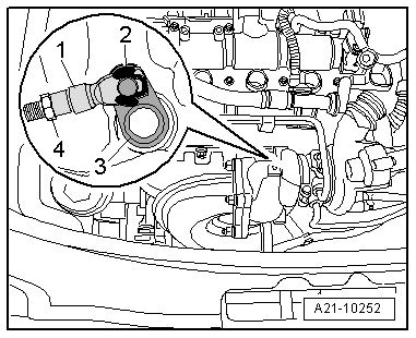
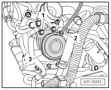
| If the nominal value is not reached, loosen the counternut -4-. |
| t
| Lever off the circlip -2- and remove the threaded piece -1- from the bolt of the operating lever -3-. |
| t
| Unscrew the threaded piece from the actuator rod sufficiently until the nominal value is reached. Fit the threaded piece each time onto the bolt of the operating lever for checking. |
| t
| Secure the threaded piece with the circlip -2- onto the bolt of the operating lever and tighten the counternut -4-. |
| Check the setting of the pressure unit |
| –
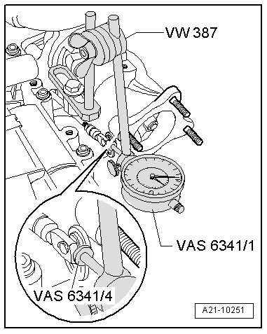
| At 0 MPa (0 bar) set the dial gauge -VAS 6341/1- to 1 mm preload. |
| –
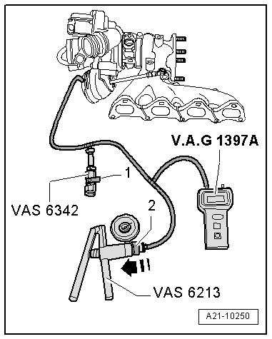
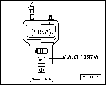
| Operate the hand vacuum pump -VAS 6213- several times until the turbocharger tester -V.A.G 1397A- indicates a pressure of 0.075...0.080 MPa (750....800 mbar). |
| –
| Release the pressure via the pressure control valve -VAS 6342- to 0.042 MPa (420 mbar). |
| –
| Read off stroke on the dial gauge -VAS 6341/1- and note. |
| –
| Release the pressure via the pressure control valve -VAS 6342- to 0 MPa (0 bar). |
| –
| Operate the hand vacuum pump -VAS 6213- several times until the turbocharger tester -V.A.G 1397A- indicates a pressure of 0.042 MPa (420 mbar). |
| –
| Read off stroke on the dial gauge -VAS 6341/1- and note. |
| –
| Calculate the mean value, to do so add the value “1” and “2” together and divide by 2. |
| –
| Operate the hand vacuum pump -VAS 6213- several times until the turbocharger tester -V.A.G 1397A- indicates a pressure of 0.075...0.080 MPa (750....800 mbar). |
| –
| Release the pressure via the pressure control valve -VAS 6342- to 0.052 MPa (520 mbar). |
| –
| Read off stroke on the dial gauge -VAS 6341/1- and note. |
| –
| Release the pressure via the pressure control valve -VAS 6342- to 0 MPa (0 bar). |
| –
| Set the readout of the dial gauge -VAS 6341/1- to “0”. |
| –
| Operate the hand vacuum pump -VAS 6213- several times until the turbocharger tester -V.A.G 1397A- indicates a pressure of 0.052 MPa (520 mbar). |
| –
| Read off stroke on the dial gauge -VAS 6341/1- and note. |
| –
| Calculate the mean value, to do so add the value “1” and “2” together and divide by 2. |
| –
| If the nominal values are not reached, repeat setting. |
| Installation occurs in reverse order for removal, while paying attention to the following: |
| t
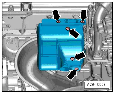
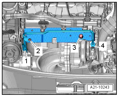
| Tightening torque of heat shield for exhaust turbocharger: 8 Nm |
| –
| Inspect coolant level, if necessary top up cooling system and bleed → Chapter. |
|
|
|
 Caution
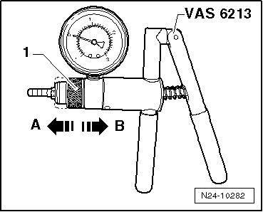
 Note
Note