
Octavia Mk2
| Disassembling and assembling pistons and conrods (Octavia II) |
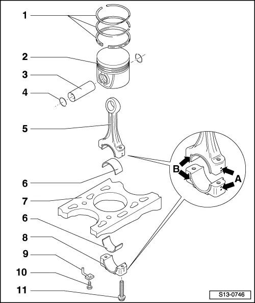
| 1 - | Piston rings |
| q | Offset joint 120° |
| q | use piston ring pliers for removing and installing |
| q | marking “TOP” faces piston crown |
| q | Inspect gap clearance → Fig. |
| q | Inspect end clearance → Fig. |
| 2 - | Piston |
| q | with combustion chamber |
| q | with oil labyrinth for cooling |
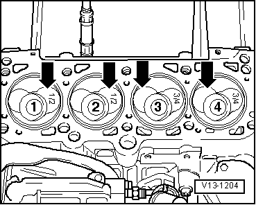
| q | mark installation position and matching cylinder |
| q | Installation position and assignment of piston/cylinder → Fig. |
| q | arrow on piston crown faces towards the belt pulley side |
| q | replace piston if there is any sign of crack formation on the piston body |
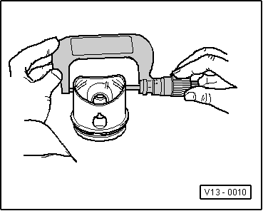
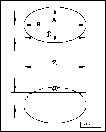
| q | Inspecting piston → Fig. |
| q | Piston: Ø 79.47 mm |
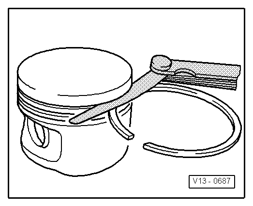
| q | use piston ring tensioning strap for installing |
| q | inspect piston projection at TDC → Chapter |
| 3 - | Piston pin |
| q | if stiff, heat piston to approx. 60°C |
| q | with drift -VW 222A- removing and installing |
| 4 - | Circlip |
| 5 - | Conrod |
| q | always replace as a set only |
| q | mark matching cylinder -A- |
| q | Fitting position: Markings -B- point towards the belt pulley side |
| q | with a split bearing cap |
| q | separate new conrod → Chapter |
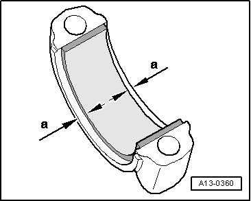
| 6 - | Bearing shell |
| q | Fitting position → Fig. |
| q | do not mix up used bearing shells (mark) |
| q | Observe version: top bearing shell (towards the piston) must be made from a long lasting material, recognition feature for new bearing shells: black marking on the contact surface near the separation point |
| q | insert in middle |
| q | check for firm seating |
| q | Axial play wear limit: 0.37 mm |
| 7 - | Cylinder block |
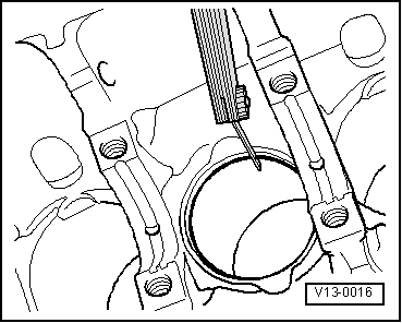
| q | inspect cylinder bore → Fig. |
| q | Cylinder: Ø 79.51 mm |
| 8 - | Conrod bearing cap |
| q | Check fitting position |
| q | cracked cover fits only in one position at the relevant conrod |
| 9 - | Oil injection nozzle |
| q | for cooling pistons |
| 10 - | 25 Nm |
| q | replace without sealant |
| 11 - | Conrod bolt, 30 Nm + torque a further + 90° (1/4 turn) |
| q | replace |
| q | oil thread and head contact surface |
| Piston ring (dimensions in mm) | New | Wear limit |
| 1. Compression ring | 0,25 … 0,40 | 1,00 |
| 2. Compression ring | 0,25 … 0,40 | 1,00 |
| Oil scraper ring | 0,25 … 0,50 | 1,00 |
|
|
| Piston ring (dimensions in mm) | New | Wear limit |
| 1. Compression ring | 0,06 … 0,09 | 0,25 |
| 2. Compression ring | 0,05 … 0,08 | 0,25 |
| Oil scraper ring | 0,03 … 0,06 | 0,15 |
|
|
 Note
Note
|
|
|
|
|
|