
Octavia Mk2
| Engine with identification characters BKC, BXE |
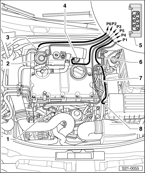
| 1 - | Vacuum reservoir |
| 2 - | Mechanical exhaust gas recirculation valve |
| 3 - | To vacuum setting element of charge pressure control |
| 4 - | Vacuum setting element for shift flap of exhaust gas recirculation radiator |
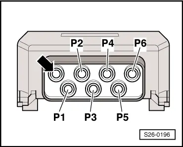
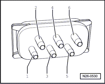
| 5 - | Valve block |
| q | Component parts of the valve block are: |
| t | Changeover valve for radiator of exhaust gas recirculation -N345- |
| t | Exhaust gas return valve -N18- |
| t | Solenoid valve for charge pressure control -N75- |
| q | Connection diagram → Fig. |
| 6 - | Vacuum line |
| q | from the tandem pump to the valve block |
| 7 - | Tandem pump |
| 8 - | Bleeder hose |
| q | to air filter |
 Note
Note
|
|