skoda Workshop Repair Guides

Skoda Workshop Service and Repair Manuals

Assembly bracket > < Securing the engine to the assembly stand
Install
Install
Installation is performed in the reverse order, pay attention to the following points:
  Note
t  When performing installation work replace the self-locking nuts.
t  Replace screws which have been tightened to a torquing angle as well as gasket rings and seals.
t  All cable straps should be fastened again in the same place when installing.
t  Secure all hose connections with corresponding hose clips.
t  Clean the drive shaft serration and hub serration on used clutch discs, remove corrosion. Apply a very thin layer of grease -G 000 100- onto the serration. Subsequently move the clutch disc up and down on the drive shaft until the hub fits smoothly on the shaft. Remove all excess grease.
–  Inspect clutch release bearing for wear, replace if necessary.
–  Slightly grease the clutch release bearing, guide bushing for clutch release bearing and serration of the drive shaft with grease -G 000 100-.
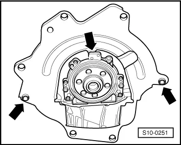
–  Check whether the dowel sleeves for centering the engine/gearbox are present in the cylinder block; insert if necessary.
   
–  Insert intermediate plate and push onto the dowel sleeves -arrows-.
–  When swiveling the unit, ensure clearance to drive shafts.
–  Align the engine mounting so that it is stress-free through tapping movements.
  Note
Tightening torques of the unit mounting → Chapter.
–  Install drive shafts → Chassis; Rep. gr.40.
Vehicles with air conditioning
–  Install AC compressor → Chapter.
–  Install the V-ribbed belt → Chapter.
Continued for all vehicles
–  Electrical connections and proper routing → Current flow diagrams, Electrical fault finding and Fitting locations.
–  Install slave cylinder → Gearbox; Rep. gr.30.
–  Attach shift mechanism → Gearbox; Rep. gr.34.
–  To facilitate the positioning of the generator, drive the bushings for the fixing screws slightly backwards
–  Install the noise insulation → Body Work; Rep. gr.50.
–  Connect coolant hoses at radiator and at heat exchanger.
–  Top up coolant → Chapter.
For engine with identification characters BCA
–  Install engine cover with air filter → Chapter.
–  On vehicles up to 05/2005, adapt the engine control unit to the EGR valve → Vehicle diagnostic, testing and information system VAS 5051.
Continued for all vehicles
–  Adapt the engine control unit to the throttle valve control unit → Vehicle diagnostic, testing and information system VAS 5051.
–  Make a test drive and interrogate the fault memory → Vehicle diagnostic, testing and information system VAS 5051.
Tightening torques
  S10-0251
Component Nm
Screws/nutsM69
 M713
 M820
 M1040
 M1270
In variation of this: 
Screws for assembly bracket → Chapter
Engine/gearbox connecting screws → Gearbox; Rep. gr.34


Assembly bracket > < Securing the engine to the assembly stand