
Superb
| Connection diagram for vacuum hoses |
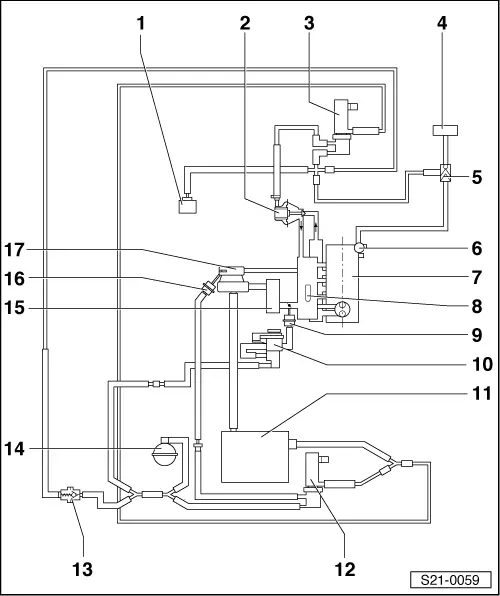
| 1 - | Vacuum setting element for shut-off valve |
| q | for the circulation of coolant in the fuel cooling system |
| q | only vehicles ► 05.02 |
| 2 - | Mechanical exhaust gas recirculation valve |
| q | Component part of the induction pipe |
| q | Must be replaced together with the induction pipe |
| 3 - | Exhaust gas return valve - N18- |
| 4 - | Brake servo unit |
| 5 - | Non-return valve |
| 6 - | Tandem pump |
| q | for fuel and vacuum supply |
| 7 - | Cylinder head |
| 8 - | Intake manifold |
| 9 - | Vacuum setting element for intake manifold flap |
| 10 - | Changeover valve for intake manifold flap -N239- |
| 11 - | Air filter |
| 12 - | Solenoid valve for charge pressure control -N75- |
| 13 - | Non-return valve |
| q | white connection points to charge pressure control solenoid valve → Item and to vacuum reservoir |
| 14 - | Vacuum reservoir |
| 15 - | Charge air cooler |
| 16 - | Vacuum setting element |
| q | for charge pressure control |
| q | Component part of the exhaust turbocharger, not replaced separately |
| 17 - | Exhaust turbocharger |