
ForTwo L3-1.0L (2009)
Tire Pressure Sensor: Description and Operation
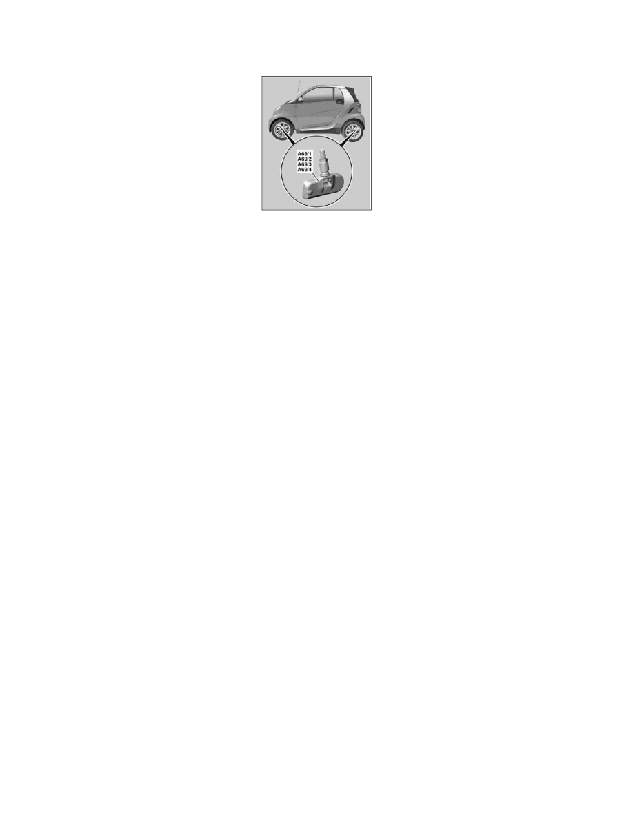
GF40.15-P-5126MCU Wheel Sensor, Component Description
A69/1
Left front TPM [RDK] wheel sensor
A69/2
Right front TPM [RDK] wheel sensor
A69/3
Left rear TPM [RDK] wheel sensor
A69/4
Right rear TPM [RDK] wheel sensor
Location
The wheel sensors are fastened securely inside the respective rim.
Task
The primary task of the TPM wheel sensors is to measure the pressure/temperature. The measuring range extends from p = 0 and 5.5 bar.
While driving the tire pressure sensors transmit six data messages every t = 60 s. Absolute pressure, tire pressure temperature, wheel identifier and status
information (manufacturer, direction of turning, operating mode) are transmitted in these data messages. The TPM [RDK] control unit (N88) receives the
data telegrams and assigns (after a learning phase) the wheel identifier to the wheels fitted to the vehicle.
As long as the TPM [RDK] control unit does not recognize the vehicle's own wheel identifier during initial commissioning, no fault message is
displayed. After replacing a tire pressure sensor in each case the new tire pressure sensor is taught in and monitored with a new wheel identifier after
driving for approx. t = 10 min.
Design
Each TPM wheel sensor is connected to the filling valve via a mounting bolt and forms an assembly unit with it. The assembly unit is attached to the rim
flange using a counternut.
The complete assembly unit has to be changed.
A wheel sensor consists of the following components:
^
Pressure sensor
^
Temperature sensor
^
High-frequency transmitter
^
Sensor battery for power supply (service life approx. 10 years)