
Forester F4-2.5L SOHC (2004)
Service limit
2.5 N (0.25 kgf, 0.56 lb)
5. SWITCH ASSEMBLY
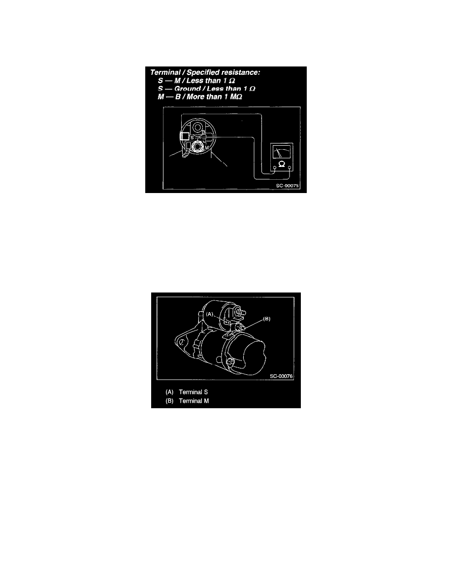
Be sure there is continuity between the terminals S and M, and between terminal S and ground. Use a circuit tester (set in "ohm").
Also check to be sure there is no continuity between terminal M and B.
6. SWITCH ASSEMBLY OPERATION
1. Connect the terminal S of switch assembly to positive terminal of battery with a lead wire, and starter body to ground terminal of battery. The
pinion should be forced endwise on shaft.
CAUTION: With the pinion forced endwise on shaft, starter motor can sometimes rotate because current flows, through pull-in coil, to motor.
This is not a problem.
2. Disconnect the connector from terminal M, and then connect the positive terminal of battery and terminal M using a lead wire and ground
terminal to starter body.
In this test set up, the pinion should return to its original position even when it is pulled out with a screwdriver.
7. PINION GAP