
Forester F4-2.5L Turbo (2009)
NOTE: Wrap sealing tape around the pressure gauge.
4) Bleed air from the pressure gauge.
5) Perform VDC sequence control.
6) When the hydraulic unit begins work, first the FL side performs compression, hold, and decompression, and then the FR side performs
compression, hold, and decompression.
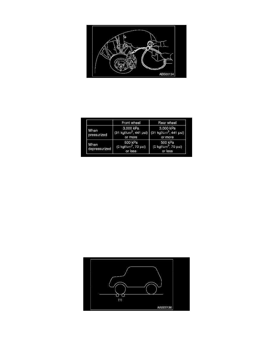
7) Read values indicated on the pressure gauge and check if the fluctuation of the values between decompression and compression meets
specification. Also, step on the brake pedal and check for any abnormal hardness or softness of the brake.
8) Disconnect the pressure gauges from FL and FR caliper bodies.
9) Install the air bleeder screws of FL and FR caliper bodies.
10) Remove the air bleeder screws from RL and RR caliper bodies.
11) Connect two pressure gauges to RL and RR caliper bodies.
12) Bleed air from RL and RR caliper bodies, and pressure gauge.
13) Perform VDC sequence control.
14) When the hydraulic unit begins work, first the RR side performs compression, hold, and decompression, and then the RL side performs
compression, hold, and decompression.
15) Read the values indicated on the pressure gauges and check if it is within specification. Also, step on the brake pedal and check for any abnormal
hardness or softness of the brake.
16) Disconnect the pressure gauge from the RL and RR caliper bodies.
17) Install the air bleeder screws of RL and RR caliper bodies.
18) Bleed air from the brake line.
CHECKING THE HYDRAULIC UNIT VDC OPERATION WITH BRAKE TESTER
1) Set wheels other than the one to measure free rollers.
2) Prepare to operate the VDC sequence control.
3) Set the front wheels or rear wheels on the brake tester and set the gear to neutral.