
Impreza Brighton Coupe AWD F4-2.2L SOHC (1997)
Torque Converter: Description and Operation
DESCRIPTION
-
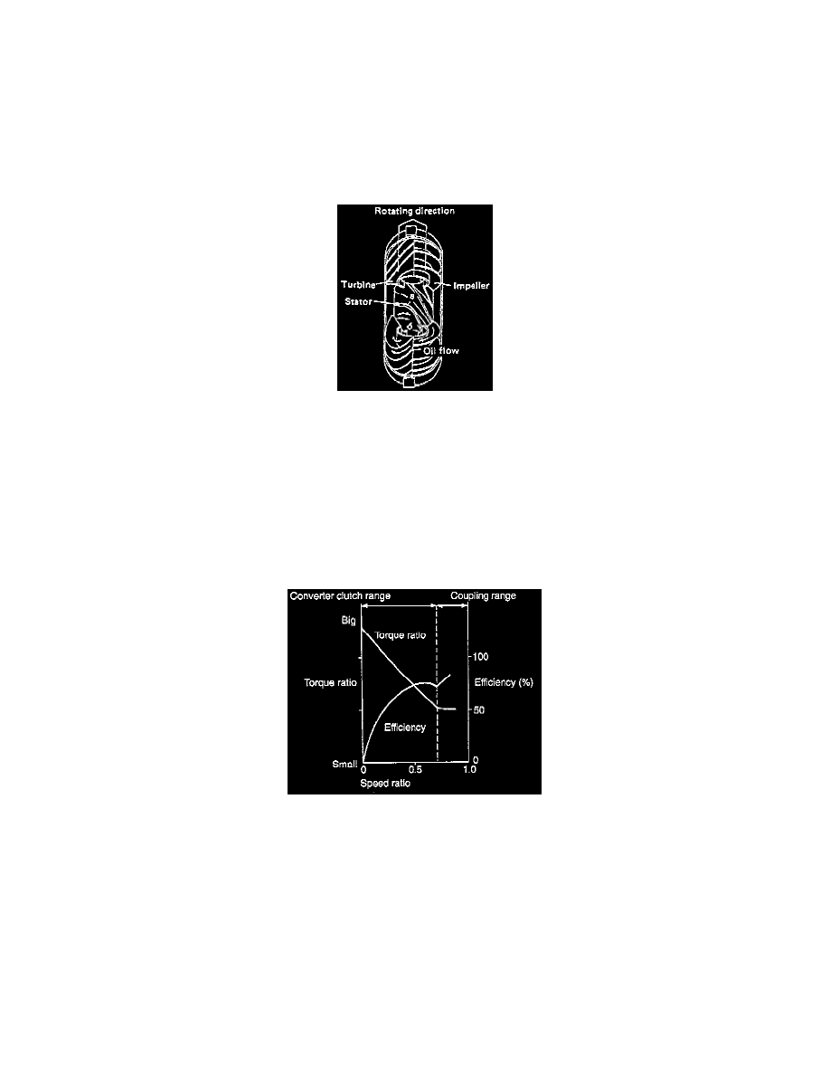
The torque converter is composed of impeller, turbine, stator, and lock-up clutch. It is filled with oil; therefore it must not be disassembled.
-
The impeller is directly coupled to the crankshaft via a drive plate. A sleeve for driving the oil pump, which is the source of the hydraulic pressure
for the automatic transmission, is welded to the rear of the impeller.
-
The turbine transmits multiplied engine torque in the torque converter clutch range, unmultiplied engine torque in the coupling range, or engine
torque itself directly through the lock-up clutch to the automatic transmission via the input shaft spline fitted to the internal spline of the turbine
hub.
-
The stator incorporates a Sprague type one-way clutch. The stator is spline-fitted to the oil pump cover via the inner race of the one-way clutch,
and secured to the torque converter clutch case.
OPERATION
When the impeller rotates, centrifugal force pushes out oil which then enters the turbine. The oil flows along the turbine blade and exerts force on the
blade. This causes the turbine to rotate and power is transmitted to the input shaft.
If turbine speed is below impeller speed, the oil leaving the turbine flows in the direction impeding impeller rotation (a in figure). This direction is
then changed by the stator so that the oil will assist impeller rotation (b in figure). With this action, the torque is multiplied.
The stator is subject to reverse torque when it changes the direction of oil flow, hence it must be secured to the casing. As turbine speed increases and
approaches impeller speed, the oil from the turbine begins to push directly on the back of the stator blade. (This changeover point is called the
"coupling point".) If the stator is still fixed under this condition, the oil flow will be impeded by the stator. To avoid this, the stator is mounted to the
case via a one-way clutch so that it can rotate freely in the same direction as the impeller and turbine.
The torque converter characteristics are shown in the graph. The torque converter clutch range refers to a range where the impeller and turbine rotate
at different speeds and the torque is multiplied by a fixed stator. In the coupling range, on the other hand, the turbine rotates at high speed, and the
stator is also rotating. The coupling range provides no torque multiplication because the torque converter clutch functions as a fluid coupling in this
range.
If the impeller (engine side) alone is rotating with stationary turbine (vehicle standstill) when the speed ratio is zero (O), this state is called the stall
point. In this state, the torque ratio of impeller and turbine is the largest. The torque ratio in this state is called the stall torque ratio, and the engine rpm
is called the stall rpm.