
Impreza GT F4-2.5L Turbo (2009)
Installation
INSTALLATION
CAUTION:
^
Be sure to use a new self-locking nut.
^
Always tighten the bushing when the arm is positioned in the state where the vehicle is at curb weight and the wheels are in full contact
with the ground.
1) Install in the reverse order of removal.
2) Inspect the wheel alignment and adjust if necessary.
Tightening torque:
Upper arm - Rear sub frame
150 N-m (15.3 kgf-m, 110.6 ft-lb)
Upper arm - Rear housing
80 N-m (8.2 kgf-m, 59 ft-lb)
Rear ABS wheel speed sensor bracket
7.5 N-m (0.76 kgf-m, 5.5 ft-lb)
Inspection
INSPECTION
1) Visually check the upper arm for damage and deformation.
2) Visually check the bushing for abnormal cracks, fatigue or damage.
Removal
Front Lateral Link
REMOVAL
1) Lift up the vehicle, and then remove the rear wheels.
2) Remove the rear trailing link.
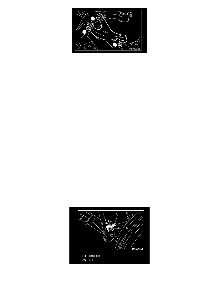
3) Remove the snap pin and nut.
4) Using a puller, remove the ball joint.