
Impreza L Sedan F4-2.2L SOHC (1997)
e. Disconnect spark plug cords from spark plugs (# 2 and # 4 cylinders).
f.
Remove under cover (LH).
g. Place suitable container under the vehicle.
h. Disconnect PCV hose from rocker cover (LH).
i.
Remove bolts, then remove rocker cover (LH).
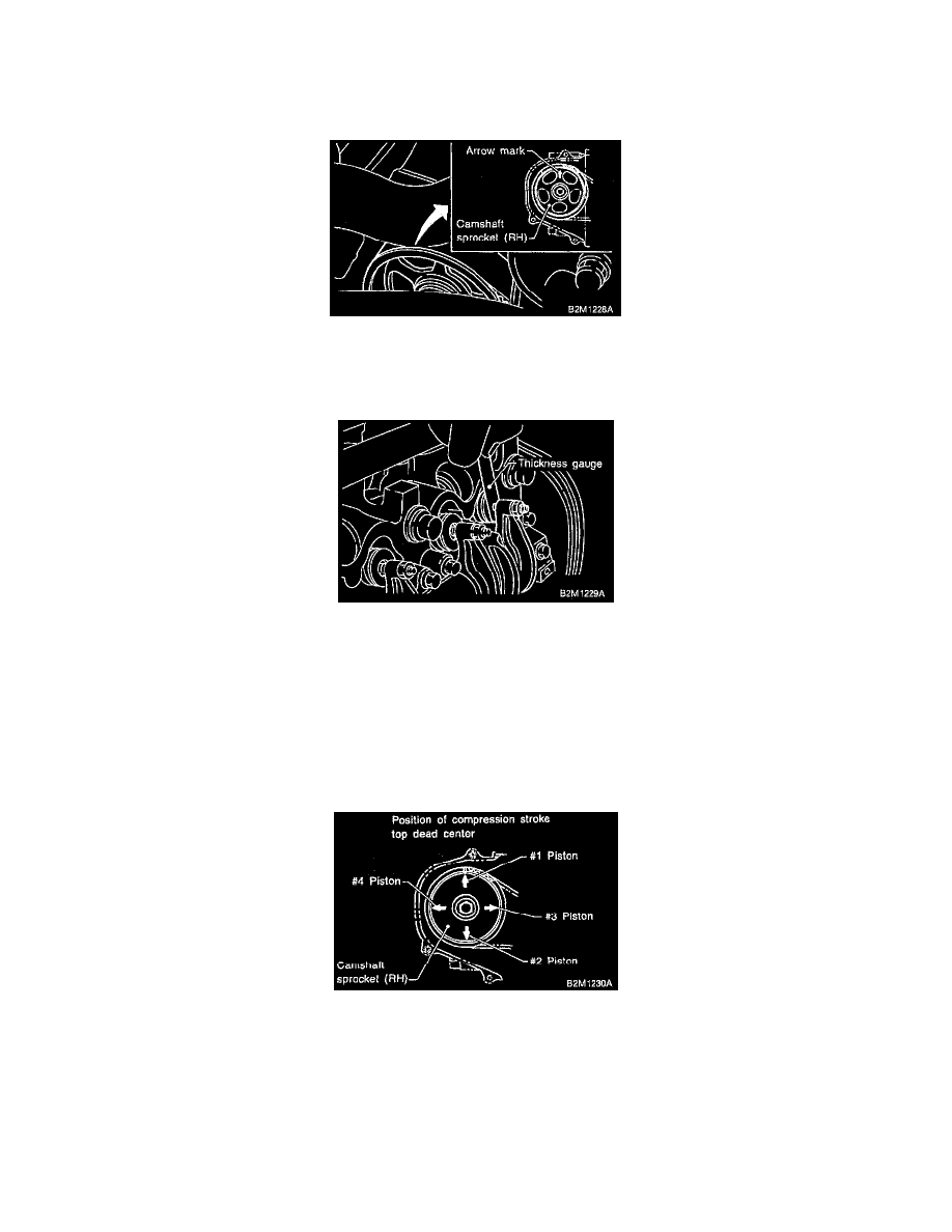
5. Set # 1 cylinder piston to top dead center of compression stroke by rotating crankshaft pulley clockwise.
NOTE: When arrow mark on camshaft sprocket (RH) comes exactly to the top, # 1 cylinder piston is brought to the top dead center of compression
stroke.
6. Measure # 1 cylinder valve clearance by using thickness gauge.
CAUTION:
^
Insert the thickness gauge in as horizontal a direction as possible with respect to the valve stem end face.
^
Measure exhaust valve clearances while lifting-up the vehicle.
Valve clearance:
Intake: 0.20 ±0.02 mm (0.0079 ±0.0008 inch)
Exhaust: 0.25 ±0.02 mm (0.0098 ±0.0008 inch)
7. If necessary, adjust the valve clearance.
8. Similar to measurement procedures used for # 1 cylinder, measure # 2, # 3 and # 4 cylinder valve clearances.
NOTE:
^
Be sure to set cylinder pistons to their respective top dead centers on compression stroke before measuring valve clearances.
^
To set # 3, # 2 and # 4 cylinder pistons to their top dead centers on compression stroke, turn crankshaft pulley clockwise 90° at a time starting
with arrow mark on righthand camshaft sprocket facing up.
9. After inspection, install the related parts in the reverse order of removal.