
Impreza L Sedan F4-2.2L SOHC (1997)
Control Module HVAC: Description and Operation
Compressor Control System
A: GENERAL
NOTE: Circuit diagram of air conditioning system.
1. When the A/C switch and fan switch are turned ON, the A/C relay activates. The compressor and F.I.C.D.* are turned on, and then the main and
sub fans also operate. Blower relay operates to direct the air flowrate determined by FAN switch position.
2. The thermo amplifier activates to stop the compressor clutch, F.I.C.D.*, and main and sub fans.
3. When the "High-Low" pressure switch operates, the compressor clutch and F.I.C.D.* stop but the main and sub fans are operating.
4. When the fan control switch operates, both the main and sub fans operate.
*1800 cc model
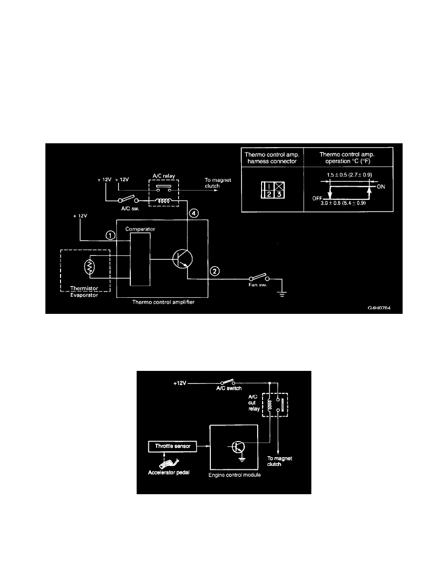
B: THERMO CONTROL AMPLIFIER
The thermo control amplifier disconnects the magnet clutch circuit to prevent the evaporator from becoming frosted when the temperature of the
evaporator fin drops close to "2 °C (36 °F)". As the evaporator is cooled, the thermistor (located on the evaporator fin) interrupts the "base" current of
the amplifier. This in turn deenergizes the A/C relay coil, which in turn disconnects the magnet clutch circuit.
C: ACCELERATION CUT SYSTEM
The A/C switch turns the A/C system on or off. The on-off operation of the switch is transmitted to the ECM.
The A/C cut relay breaks the current flow to the compressor, through the use of an output signal from the ECM, for a certain period of time when a
"full-throttle" signal (emitted from the throttle sensor) enters the ECM while the compressor is operating. This prevents the degradation of acceleration
performance and stabilizes the main fuse box located on the left side of the engine compartment.