
Impreza L Sedan F4-2.2L SOHC (1997)
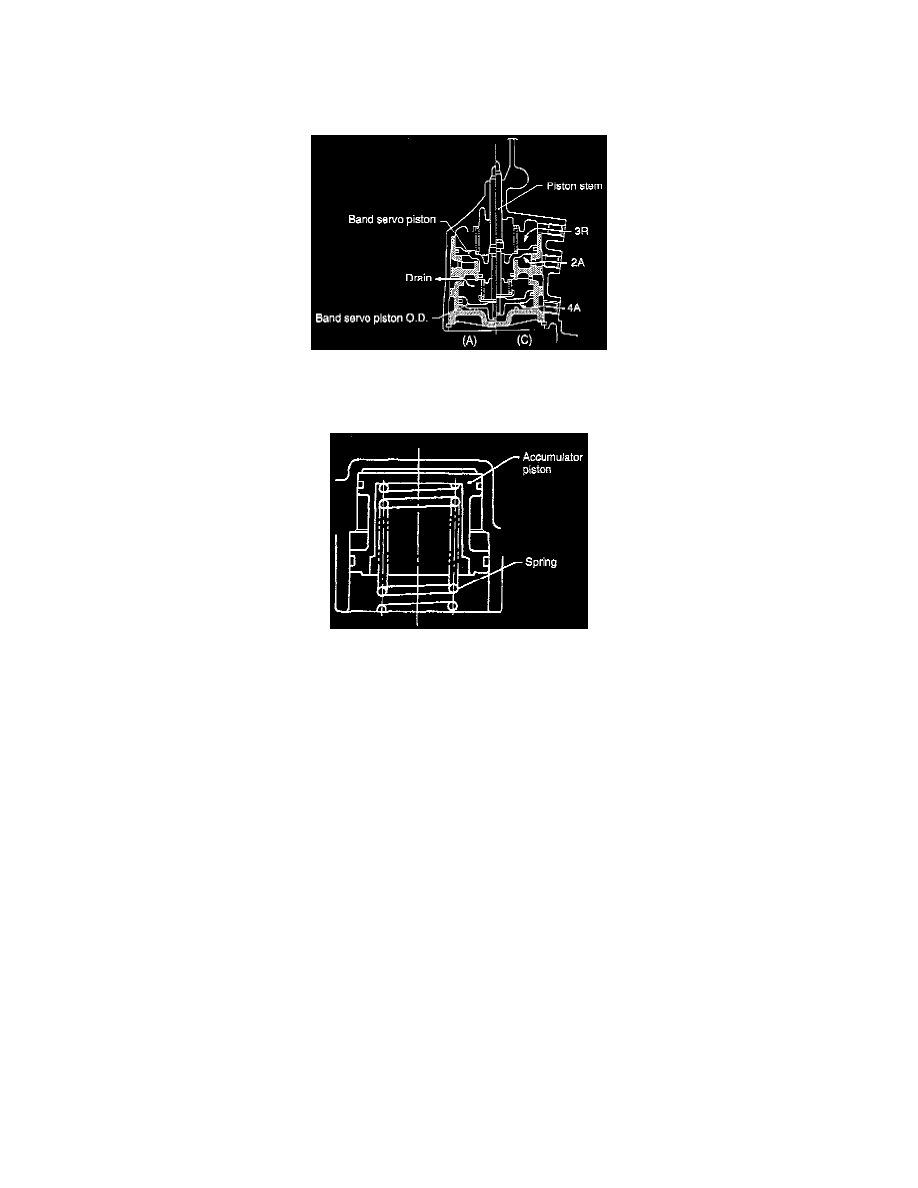
Next, when the release pressure 3R to the servo chamber (I) and the hydraulic operating pressure 2A to the servo chamber (II) are applied
simultaneously, the band servo piston is pushed downward by the force of the return spring and the pressure difference between chamber (I) and
chamber (II), caused by the difference in operating areas of the band servo pistons. Under this condition, state (A) is resumed, and the brake band
loosens and releases the reverse clutch drum. (3rd speed state)
When hydraulic pressure 4A is applied to the servo chamber (III) under the 3rd speed condition, the band servo piston O.D. is brought into contact
with the retainer installed at the lower end of the band servo piston stem. Hence, the stem is pushed upward. As a result, state (C) is achieved where
the brake band slowly tightens the reverse clutch drum and fixes the front sun gear of the front planetary gear. (4th speed state)
The accumulator is built into the transmission case as shown. When hydraulic pressures 2A, 3R, and 4A are applied from the hydraulic control unit to
the respective servo chambers, the hydraulic shock loads are absorbed by the accumulator. This is because the accumulator piston moves slowly, and
the brake band is tightened or released slowly. This results in smooth gearshift operation.