
Impreza WRX STI F4-2.5L DOHC Turbo (2007)
Hydraulic Control Assembly - Antilock Brakes: Service and Repair
ABS Control Module and Hydraulic Control Unit (ABSCM&H/U)
REMOVAL
1) Disconnect the ground cable from battery.
2) Remove the air intake duct and air cleaner case from the engine compartment to facilitate removal of ABSCM&H/U.
3) Use compressed air to get rid of water around the ABSCM&H/U.
NOTE: Contact will be insufficient if the terminal gets wet.
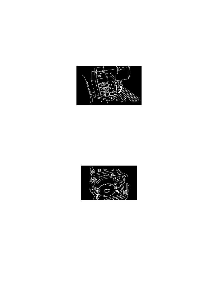
4) Disconnect the ABSCM&H/U connector pulling up the lock lever.
CAUTION: Do not pull the harness when disconnecting connector.
5) Remove the harness clip.
6) Disconnect the brake pipes from ABSCM&H/U.
7) Wrap the brake pipe using a vinyl bag not to spill the brake fluid on the vehicle body.
CAUTION: When brake fluid is attached to the vehicle body, wash it off with water and wipe the water.
8) Remove the nuts and remove the ABSCM&H/U.
CAUTION:
^
Do not drop or bump the ABSCM&H/U.
^
Do not turn ABSCM&H/U upside down or place it sideways for storage.
^
Be careful that no foreign objects are mixed in ABSCM&H/U.
^
Be careful that no water enters inside the connectors.
9) Remove the ABSCM&H/U bracket.
INSTALLATION
1) Install the ABSCM&H/U bracket.
Tightening torque:33 Nm (3.3 kgf-m, 24 ft. lbs.)
2) Install the ABSCM&H/U aligning the groove of damper on ABSCM&H/U side with the pawl of bracket.
NOTE: Check the identification mark of ABSCM&H/U.
Tightening torque:7.5 Nm (0.76 kgf-m, 5.5 ft. lbs.)