
Justy L3-1189cc 1.2L (1987)
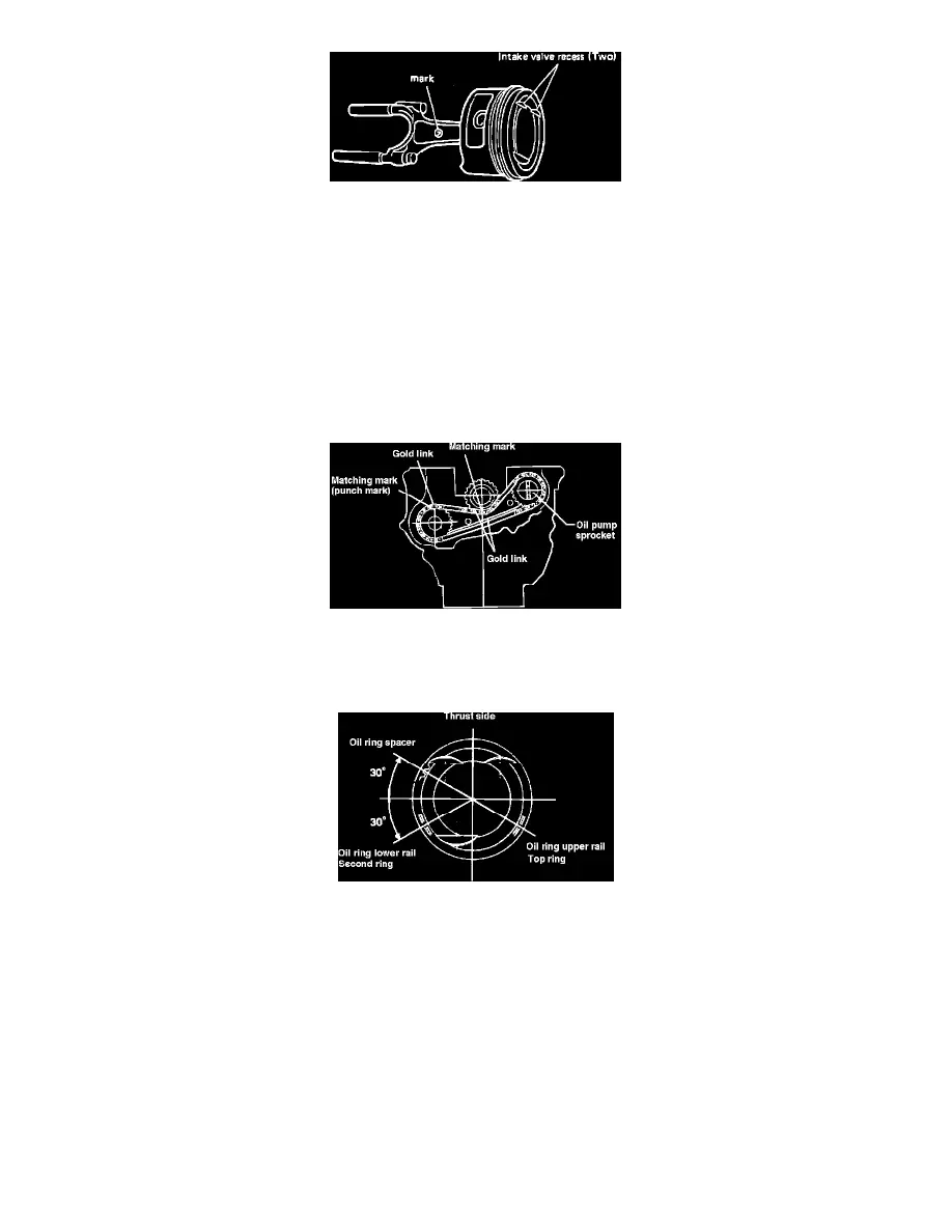
Fig. 33 Assembling Piston To Connecting Rod
16.
Assemble piston to connecting rod so that intake valve recesses on piston and crescent mark on connecting rod are positioned as shown, Fig. 40.
17.
Install rings onto pistons. Ensure R1 (top ring) and R2 (second ring) marks on compression rings face upward.
18.
Install balancer shaft and oil pump sprocket, then temporarily install chain guide. If replacing chain and/or chain guide, always replace them in the
following combinations:
a. If replacing chain only, replacement chain should have green color identification.
b. If replacing chain guide only, and original chain guide is white, replacement guide should have white color identification. If original chain
guide is blue, replacement guide should have blue color identification. If original chain guide is green, replacement guide should have white
or blue color identification.
c. If replacing chain and chain guide, and original chain guide is white or blue, replacement guide should be same as original, and replacement
chain should have green color identification.
19.
Install main bearing halves into crankcase.
Fig. 41 Installing drive chain. 3-73/1200cc engine
20.
Install chain and crankshaft, then align marks on sprockets with gold links on chain as shown in Fig. 41.
21.
Install main bearing caps with arrows facing front of engine, then torque cap retaining bolts to 30-35 ft.lbs.
Fig. 42 Piston ring installation. 3-73/1200cc engine
22.
Position ring end gaps as shown, Fig. 42, then install piston/rod assemblies into cylinders. Ensure intake valve recesses on piston face intake
manifold side of engine.
23.
Install connecting rod bearing caps and torque to 29-33 ft.lbs.
24.
Install rear oil seal using suitable tools.
25.
Install crankcase cover together with air suction manifold bracket.
26.
Install oil pump inner rotor, outer rotor and cover. Ensure inner rotor shaft aligns with groove in sprocket.
27.
Install water pump as follows:
a. Coat outer circumference of new water pump seal with Three-Bond 1303 sealant or equivalent, then drive seal into crankcase cover.
b. Coat seal lip with coolant, then press pump impeller against balancer shaft and measure tip clearance. Tip clearance should be .012-.035 inch.
If clearance is not as specified, add spacers as required.
c. Position screwdriver between balancer shaft weight and crankcase, then install impeller attaching bolt and torque to 8 ft.lbs.
d. Install water pump cover using new gasket.
28.
Install oil pan using new gasket. Torque attaching bolts to 4 ft.lbs.
29.
Install flywheel housing.