
Legacy GT LTD Sedan AWD F4-2.5L DOHC (1998)
Function
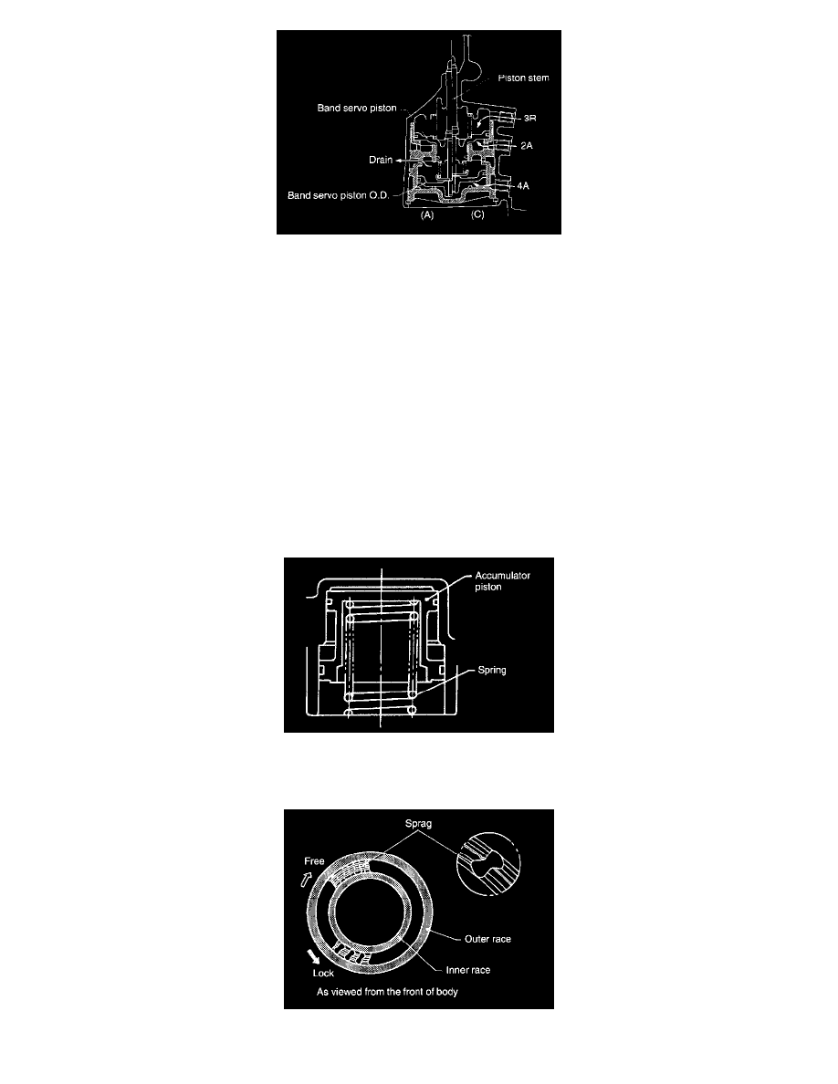
One end of the brake band is secured to the transmission case via the brake band adjusting screw.
When no hydraulic pressure is applied to the servo piston from the hydraulic pressure controller, the servo piston and band servo piston O.D. are
forced downward by the return spring, as shown in (A) of the Figure.
When hydraulic pressure 2A is applied to the servo chamber (II), it causes the band servo piston to come into contact with the stepped portion of the
band servo piston stem, thereby pushing the band servo piston stem upward to state (B). Under this condition, the brake band slowly tightens the
reverse clutch drum and fixes the front sun gear of the front planetary gear. (2nd speed state)
Next, when the release pressure 3R to the servo chamber (I) and the hydraulic operating pressure 2A to the servo chamber (II) are applied
simultaneously, the band servo piston is pushed downward by the force of the return spring and the pressure difference between chamber (I) and
chamber (II), caused by the difference in operating areas of the band servo pistons. Under this condition, state (A) is resumed, and the brake band
loosens and releases the reverse clutch drum. (3rd speed state)
When hydraulic pressure 4A is applied to the servo chamber (III) under the 3rd speed condition, the band servo piston O.D. is brought into contact
with the retainer installed at the lower end of the band servo piston stem. Hence, the stem is pushed upward. As a result, state (C) is achieved where
the brake band slowly tightens the reverse clutch drum and fixes the front sun gear of the front planetary gear. (4th speed state) The accumulator is
built into the transmission case as shown in the Figure. When hydraulic pressures 2A, 3R, and 4A are applied from the hydraulic control unit to the
respective servo chambers, the hydraulic shock loads are absorbed by the accumulator. This is because the accumulator piston moves slowly, and the
brake band is tightened or released slowly. This results in smooth gearshift operation.
9. ONE-WAY CLUTCH
Construction
The One-Way Clutch (O.W.C.) is a Sprague type. Two clutches are used. One is mounted between the one-way clutch outer race and the rear internal
gear ASSY. The other is located between the forward clutch drum and the one-way clutch inner race.
Function