
Legacy Outback Ltd Sedan F4-2.5L SOHC (2000)
Front Cross-Member: Service and Repair
REMOVAL
1. Disconnect ground cable from battery.
2. Lift-up vehicle and remove front tires and wheels.
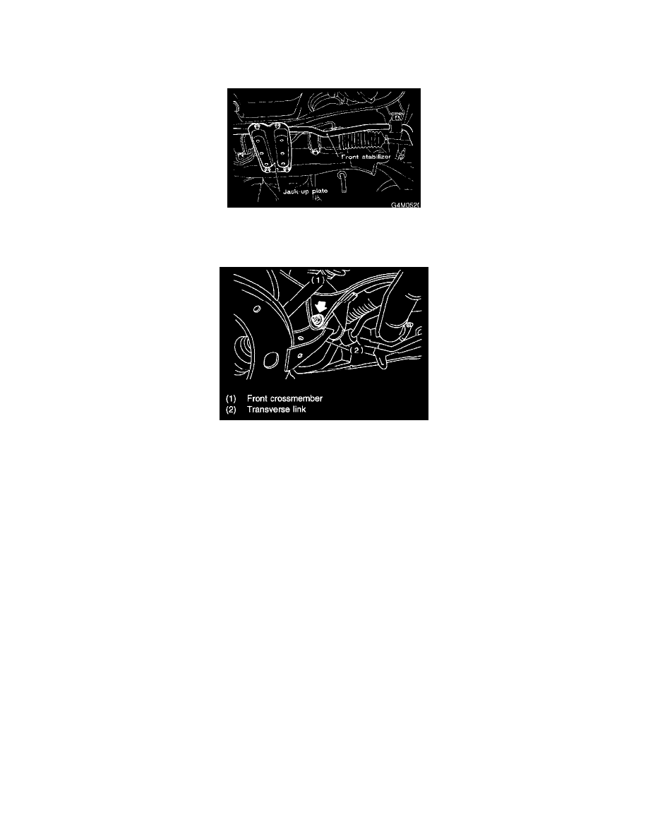
3. Remove both stabilizer and jack-up plate.
4. Disconnect tie-rod end from housing.
5. Remove front exhaust pipe.
6. Remove front transverse link from front crossmember and bode
7. Remove nuts attaching engine mount cushion rubber to crossmember.
8. Remove steering universal joint.
9. Disconnect power steering pipe from steering gear box.
10. Lift engine by approximately 10 mm (0.39 inch) by using chain block.
11. Support crossmember with a jack, remove nuts securing crossmember to body and lower crossmember gradually along with steering gearbox.
CAUTION: When removing crossmember downward, be careful that tie-rod end does not interfere with SFJ boot.
INSTALLATION
1. Installation is in the reverse order of removal procedures.
CAUTION: Always tighten rubber bushing when wheels are in full contact with the ground and vehicle is curb weight.
Tightening torque:
Transverse link bushing to crossmember: 9 ± 15 Nm (10.0 ± 1.5 kg-m, 72 ± 11 ft. lbs.)
Stabilizer to bushing: 25 ± 4 Nm (2.5 ± 0.4 kg-m, 18.1 ± 2.9 ft. lbs.)
Tie-rod end to housing: 27.0 ± 2.5 Nm (2.75 ± 0.25 kg-m, 19 ± 1.8 ft. lbs.)
Front cushion rubber to crossmember: 74 +10/-5 Nm (7.5 +1.0/-0.5 kg-m 54.2 +7.2/-3.6 ft. lbs.)
Universal joint to pinion shaft: 24 ± 3 Nm (2.4 ± 0.3 kg-m, 17.4 ± 2.2 ft. lbs.)
Crossmember to body: 98 ± 15 Nm (10.05 ± 1.5 kg-m, 72 ± 11 ft. lbs.)
2. Purge air from power steering system.
NOTE: Check wheel alignment and adjust if necessary.