
Legacy Sedan 4WD F4-2.2L SOHC (1992)
Vehicle Speed Sensor: Testing and Inspection
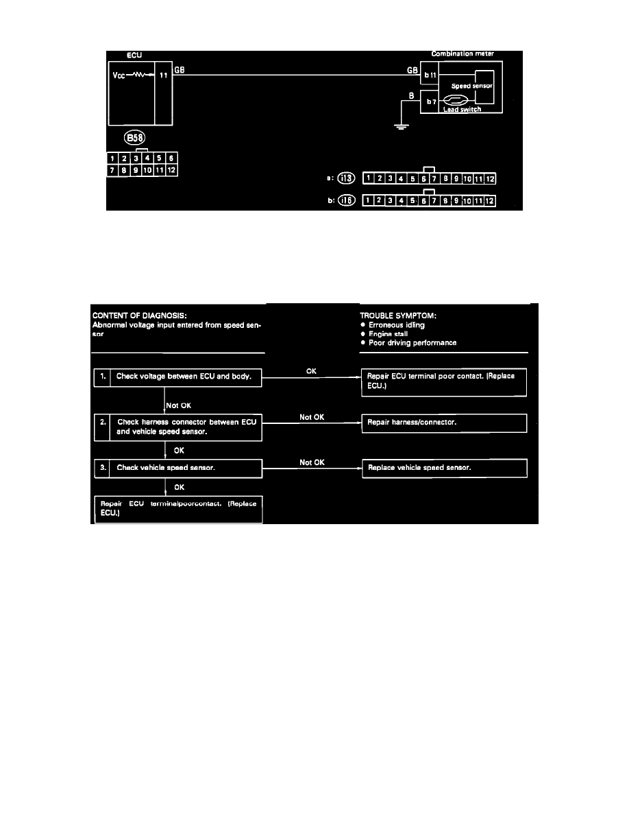
Vehicle Speed Sensor Schematic
A faulty vehicle speed sensor will set code 33 in the on-board diagnostic system. Refer to the schematic diagram and test the sensor with the diagnostic
chart.
VEHICLE SPEED SENSOR DIAGNOSTIC CHART
Vehicle Speed Sensor Diagnostic Chart
CHECK ECU VOLTAGE
1. Raise and support vehicle with safety stands.
CAUTION: On 4WD models, ensure that all four wheels are off the ground.
2. While driving wheels are slowly turning, measure voltage between ECU connector terminal (B58)11 and ground. It should oscillate between 0V
and 5V.
CHECK HARNESS BETWEEN ECU AND SPEED SENSOR
1. Disconnect ECU and combination meter connectors.
2. Measure resistance between ECU and combination meter connectors and ground as follows:
Connector & terminal:
Resistance:
(B58)11-(i16)11
0 Ohms
(i16)11-Ground
1M Ohms min.
(i16)7-Ground
0 Ohms
CHECK VEHICLE SPEED SENSOR