
Outback F6-3.0L DOHC (2006)
Fuel Gauge: Description and Operation
FUEL GAUGE
GENERAL
-
The fuel gauge unit consists of a float and a potentiometer whose resistance varies depending on movement of the float. It is located inside the fuel
tank and forms an integral part of the fuel pump. The fuel gauge indicates the fuel level in the tank when the ignition switch is in the ON position.
When the trip knob is pushed, the fuel gauge illumination comes ON and the fuel level registered just before the ignition switch was turned OFF is
indicated, even when the ignition switch is in the OFF position.
-
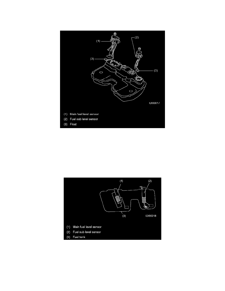
All models are equipped with two fuel level sensors. These sensors are installed in the fuel tank, one on the right side and the other on the left side.
Two sensors are necessary because the fuel tank is divided into main and sub tank compartments.
OPERATION
The low fuel warning light operates as follows:
-
The signal from the fuel level sensor is converted into a digital signal at the body integrated unit, and then sent to the combination meter. The
combination meter microprocessor continually monitors this signal. It turns on the low fuel warning light in the combination meter if a resistance
value corresponding to the critical fuel level is detected for a certain time while driving.
-
This monitoring time has been decided to avoid false operation of the warning light, which may happen when a large part of remaining fuel is
collected temporarily in the sub tank compartment.