
Outback L.L.Bean Edition AWD F6-3.0L (2002)
6. Slide the drive pinion gauge scale with fingertip and read the value at the point where it matches with the end face of drive pinion.
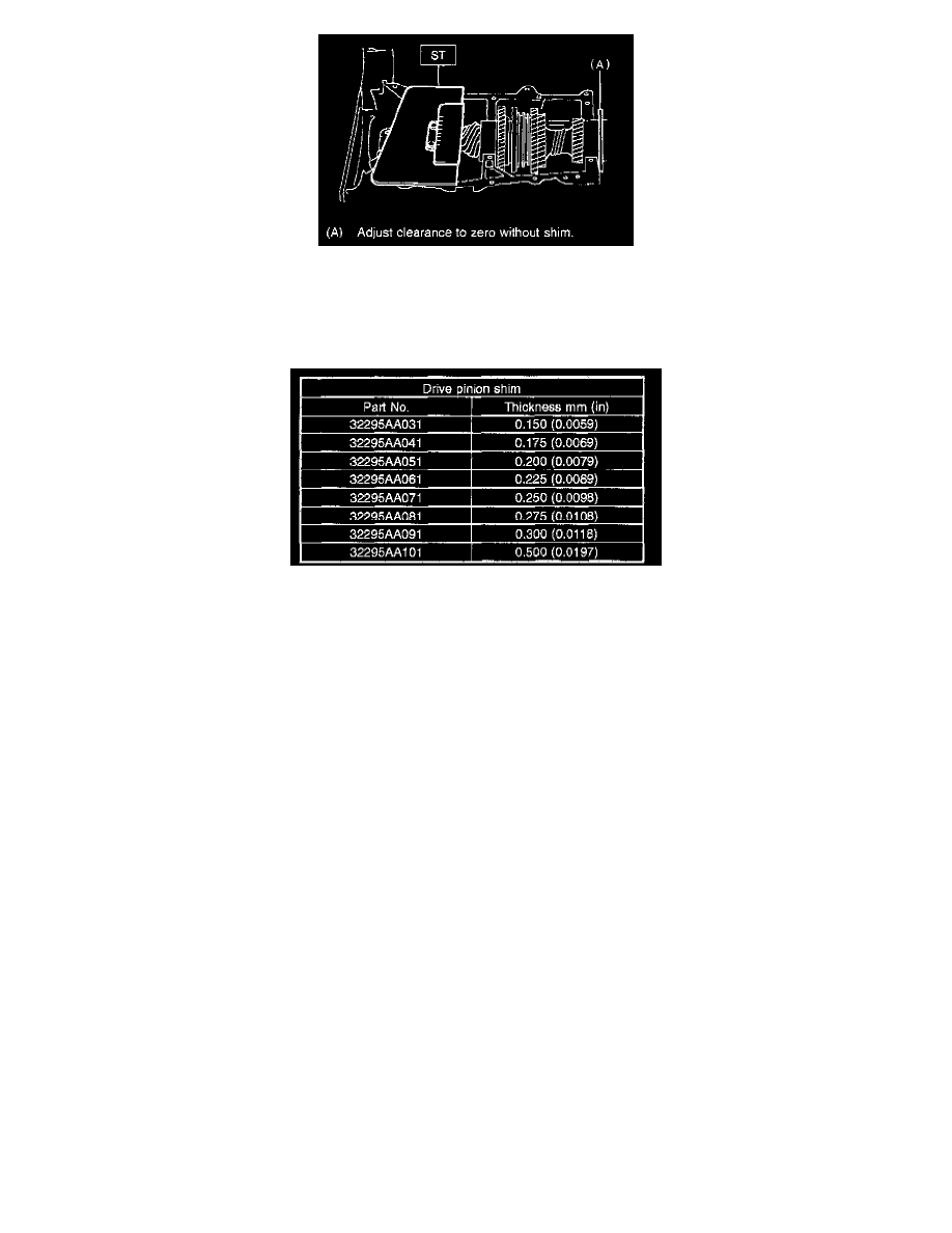
ST 499917500 DRIVE PINION GAUGE ASSY
7. The thickness of shim shall be determined by adding the value indicated on drive pinion to the value indicated on the ST. (Add if the number on
drive pinion is prefixed by + and subtract if the number is prefixed by -.)
ST 499917500 DRIVE PINION GAUGE ASSY
8. Select one to three shims from the next table for the value determined as described above and take a shim thickness, which is closest to the said
value.
9. Install differential assembly.
10. Set transmission main shaft assembly and drive pinion assembly in position. (So there is no clearance between the two when moved all the way to
the front). Inspect suitable 1st-2nd, 3rd -4th and 5th shifter fork so that coupling sleeve and reverse driven gear are positioned in the center of their
synchronizing mechanisms.
11. Install transmission case.
12. Install transfer case with extension case assembly.
13. Install the manual transmission assembly to vehicle.