
Outback Sport F4-2.5L SOHC (2005)
Electronic Brake Control Module: Testing and Inspection
INSPECTION
1. Check the connected and fixed condition of connector.
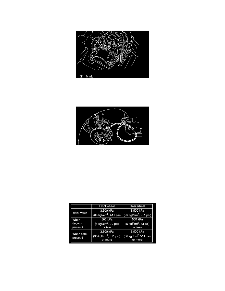
2. Check the mark used for ABSCM&H/U identification.
Refer to "SPECIFICATION" for mark.
CHECKING THE HYDRAULIC UNIT ABS OPERATION BY PRESSURE GAUGE
1. Lift-up the vehicle, and then remove the wheels.
2. Remove the air bleeder screws from the FL and FR caliper bodies.
3. Connect two pressure gauges to the FL and FR caliper bodies.
CAUTION:
^
Pressure gauges used exclusively for brake fluid must be used.
^
Do not use the pressure gauge for the measurement of transmission oil pressure since the piston seal may be expanded and deformed.
NOTE: Wrap a sealing tape around the pressure gauge.
4. Bleed air from the pressure gauges and the FL and FR caliper bodies.
5. Perform ABS sequence control.
6. When the hydraulic unit begins to work, first the FL side performs decompression, holding and compression, and then the FR side performs
decompression, holding and compression.
7. Read values indicated on the pressure gauge and check if the fluctuation of the values between decompression and compression meets the standard
values. Depress the brake pedal and check that the kick-back is normal, and tightness is normal.
8. Remove the pressure gauges from the FL and FR caliper bodies.
9. Connect the air bleeder screws of the FL and FR caliper bodies.
10. Remove the air bleeder screws from the RL and RR caliper bodies.
11. Connect two pressure gauges to the RL and RR caliper bodies.
12. Bleed air from the brake system.
13. Bleed air from the pressure gauges and the RL and RR caliper bodies.