
SVX FWD L6-3.3L DOHC (1994)
2) Measure voltage between ECU connector and body.
Connector & Terminal/Specified value
(B62) No. 14 - Body/10 V, min.
2.
CHECK HARNESS CONNECTOR BETWEEN ECU AND MAIN RELAY.
1) Turn ignition switch to "OFF".
2) Disconnect connector from ECU and main relay.
3) Measure resistance of harness connector between ECU and main relay.
Connector & Terminal/Specified value
(B62) No. 14 - (B52) No. 4/0 ohms
3.
CHECK POWER SUPPLY CIRCUIT OF MAIN RELAY.
1) Turn ignition switch to "ON".
2) Measure voltage between main relay connector and body.
Connector & Terminal/Specified value
(B52) No. 1 - Body/10 V, min.
(B52) No. 2- Body/10 V, min.
4.
CHECK INPUT SIGNAL FROM BY-PASS AIR CONTROL SOLENOID VALVE.
1) Turn ignition switch to "ON".
2) Measure voltage between ECU connector and body.
Connector & Terminal/Specified value
(B62) No. 2 - Body/7 V, min.
(B62) No. 1 - Body/6 V, min.
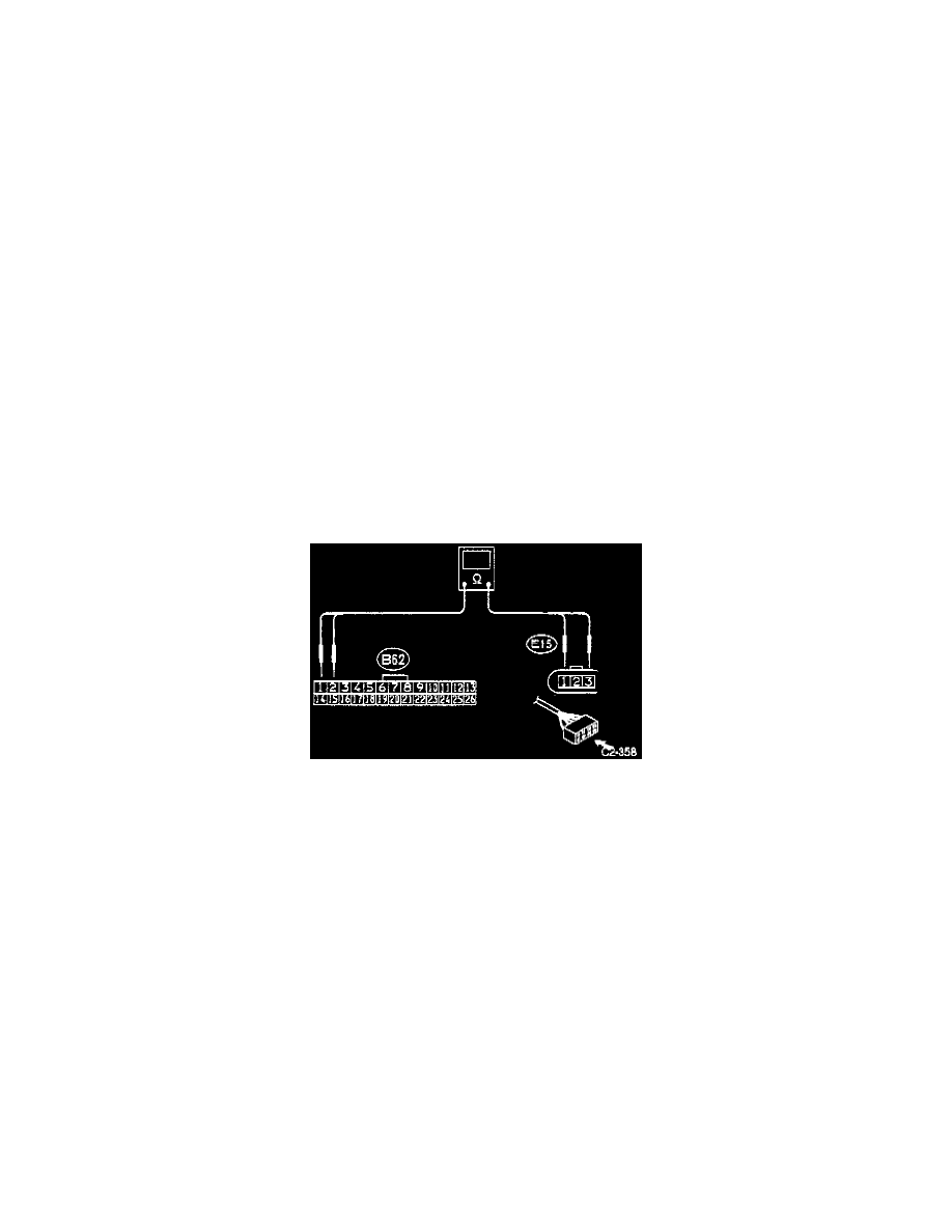
By-Pass Air Control Solenoid Valve and ECM Connectors
5.
CHECK HARNESS CONNECTOR BETWEEN ECU AND SOLENOID VALVE.
1) Turn ignition switch to "OFF".
2) Disconnect ECU connectors.
3) Separate throttle body from collector, and disconnect connector from by-pass air control solenoid valve.
4) Measure resistance of harness connector between ECU and solenoid valve.
Connector & Terminal/Specified value
(B62) No. 2 - (E15) No. 3/0 ohm
(B62) No. 1 - (El 5) No. 1/0 ohm