
XT-6 2WD L6-2.7L SOHC (1989)
39.
Install flywheel housing. Tighten bolts to specifications.
40.
Install oil pan. Tighten bolts to specifications.
41.
Install cylinder heads as previously described.
42.
Install flywheel or driveplate. Tighten bolts to specifications.
43.
On models with manual transmission, install clutch disc and pressure plate, then diagonally torque attaching bolts to specifications. When
installing pressure plate, ensure ``0'' marks on pressure plate and flywheel are positioned at least 120° apart.
44.
On all models, install water pump using new gasket and seal.
45.
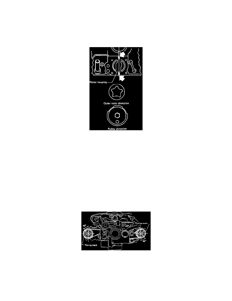
Oil Pump installation:
Fig. 26 Installing Oil Pump
a. Apply a small amount of Three-Bond 1207B sealant or equivalent to crankcase as indicated by arrows in Fig. 26. Ensure no excess sealant
enters rotor chamber.
b. Apply engine oil to rotor housing, then install outer rotor into housing and position as shown, Fig. 26.
c. Position oil pump pulley as shown, then install oil pump assembly.
46.
Install valve lash adjusters, rockers, camshaft cases and rocker covers as outlined previously.
47.
Install timing belts and center belt cover as previously described.
48.
Lock crankshaft at flywheel, then install crankshaft pulley. Tighten bolts to specifications.
49.
Install pulley and pulley cover to water pump, then tighten bolts temporarily.
50.
Apply engine oil to O-ring on dipstick tube, then install dipstick tube and dipstick.
51.
Install oil filler duct and bracket.
52.
Install water pump, water bypass pipe, hose and water pipe using new O-rings.
53.
Install knock sensor, if removed, then the alternator brackets.
54.
Install PCV connector and harness clamp.
55.
Install intake manifold, then reconnect hoses, lines and electrical connections.
56.
Install alternator.
Fig. 23 Positioning No. 1 Cylinder At TDC
57.
Position No. 1 cylinder at TDC, ensuring camshaft sprocket timing marks are positioned as shown, Fig. 23.
58.
Align mark on distributor housing with mark on distributor gear, then install distributor and mounting bolt.
59.
Reconnect distributor electrical wiring, then install left and right timing covers.
60.
Install drive belt. Refer to DRIVE BELT SERVICE for belt routing and tension data.
61.
Torque water pump pulley attaching bolts to specifications.