
XT-6 2WD L6-2.7L SOHC (1989)
Throttle Position Sensor: Adjustments
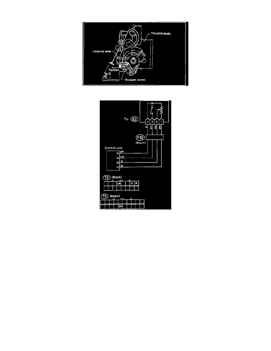
Throttle Sensor Adjustment
Throttle Position Sensor Circuit
1.
Remove throttle sensor connector.
2.
Insert a thickness gauge (0.35mm, 0.0138in) between throttle body stopper screw and stopper (portion "G"). Resistance between terminals "3" and
"4" should be 5k ohms maximum.
4.
Replace first thickness gauge with a second (0.75mm, 0.0295in Resistance between terminals "3" and "4" should be 1M ohms minimum.
4.
Resistance between terminals "1" and "4" should be 3-7k ohms.
5.
Measure resistance between terminals "2" and "4". It should be 4.2-15k ohms with throttle fully closed and 0.1-11k ohms with throttle fully
opened.
6.
Ensure that resistance changes smoothly between fully opened and fully closed throttle positions.
7.
If resistance is out of specification, replace sensor.