
Aerio L4-2.3L (2006)
6) After installing three rings (1st, 2nd and oil rings), distribute their end gaps as shown in figure.
Pistons, Piston Rings, Connecting Rods and Cylinders Inspection and Cleaning
Clean carbon from piston head and ring grooves, using a suitable tool.
Cylinder
^
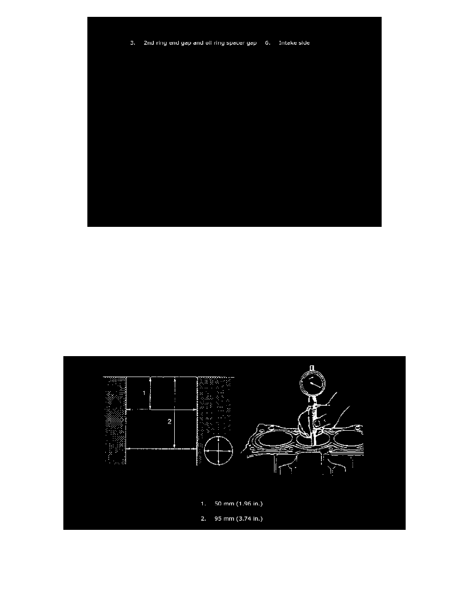
Inspect cylinder walls for scratches, roughness, or ridges which indicate excessive wear. If cylinder bore is very rough or deeply scratched, or
ridged, rebore cylinder and use over size piston.
^
Using a cylinder gauge, measure cylinder bore in thrust and axial directions at two positions as shown in figure. If any of conditions is noted,
rebore cylinder.
1) Cylinder bore diameter exceeds limit.
2) Difference of measurements at two positions exceeds taper limit.
3) Difference between thrust and axial measurements exceeds out-of-round limit.
Cylinder bore diameter limit: 84.050 mm (3.3090 inch)
Taper and out-of-round limit: 0.10 mm (0.004 inch)
NOTE: If any one of four cylinders has to be rebored, rebore all four to the same next oversize. This is necessary for the sake of uniformity and