
Esteem L4-1590cc 1.6L SOHC 0 MFI 16V (1995)
Connecting Rod Bearing: Service and Repair
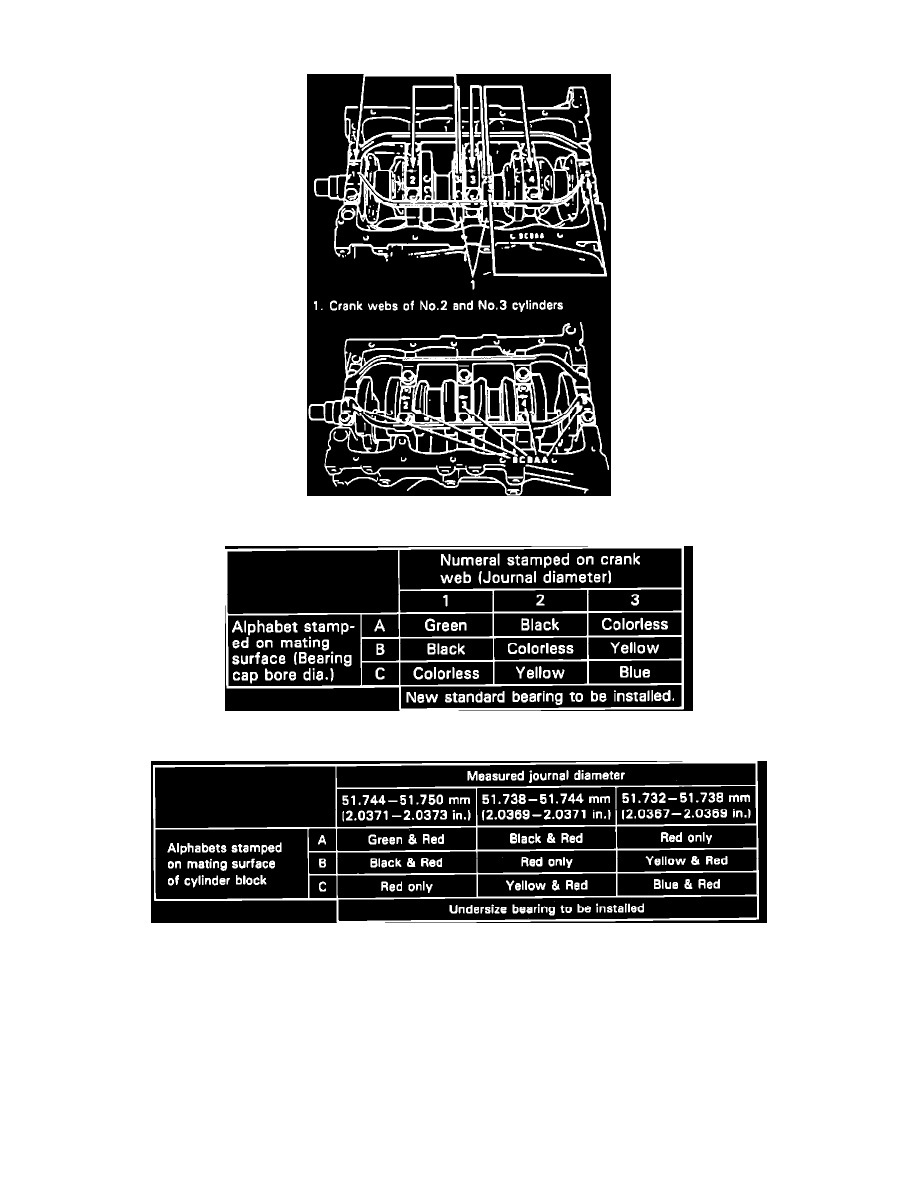
Fig. 32 Crank Web Numbers & Main Bearing Cap Bore Letters Locations
Fig. 33 Standard Size Main Bearing Selection Chart
Fig. 34 0.25 Mm Undersize Main Bearing Selection Chart
Select new standard size main bearings as follows:
1. Crank webs of No. 2 and No. 3 cylinders have 5 stamped numbers on them, Fig. 32. These numbers represent journal diameters at bearing caps 1,
2, 3, 4 and 5 respectively. These numbers, 1, 2 and 3, represent the following diameters: number 1, 2.0470-2.0472 inch; number 2, 2.0468-2.0470
inch and number 3, 2.0465-2.0468 inch.
2. Mating surface of cylinder block has 5 letters stamped on it, Fig. 32. These letters represent main bearing cap bore diameters at bearing caps 1, 2,
3, 4 and 5 respectively. These letters, A, B and C, represent the following diameters: A, 2.2047-2.2050 inch; B, 2.2050-2.2052 inch and C,
2.2052-2.2054 inch.
3. There are 5 standard bearing thicknesses, distinguished by paint marks as follows: green, 0.0786-0.0787 inch; black, 0.0787-0.0788 inch;
colorless, 0.0788-0.0789 inch; yellow, 0.0789-0.0790 inch and blue, 0.0790-0.0791 inch.
4. Using numbers stamped on No. 2 and No. 3 crank webs and letters stamped on mating surface of cylinder block, determine new bearing to be