
Grand Vitara 2WD V6-2.5L (2004)
^
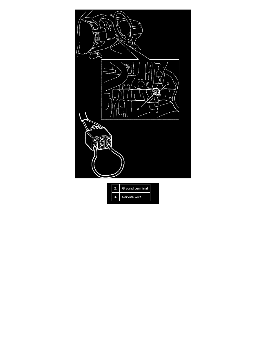
When Diag. switch "PINK" wire terminal (2) of blue diagnosis connector (1) (monitor connector) is grounded, the abnormal area is output as
DTC. It is indicated by flashing of "ABS" warning lamp. (Refer to the following table.)
^
For procedure to clear all DTC's, refer to DTC Clearance: Type 1.
Also ABS control module turns ON EBD warning lamp (brake warning lamp) depending on the trouble that detected by the module and EBD
warning lamp does not indicate DTC as well as "ABS" warning lamp.
Fail-Safe Function
When an abnormality occurs (an abnormal DTC is detected), ABS control module turns OFF the fail-safe relay (transistor) which supplies power to
itself. Thus, with ABS not operating, brakes function just like the brake system of the vehicle without ABS.
Fail-Safe Operation
When ABS hydraulic unit/control module detects malfunction, when ABS hydraulic unit/control module enters fail-safe mode and ABS hydraulic
unit/control module turns off ABS or EBD operation.