
Grand Vitara 2WD V6-2.7L (2006)
6. Remove ABS (ESP) hydraulic unit / control module with bracket from vehicle by removing bracket bolt and two bracket nuts.
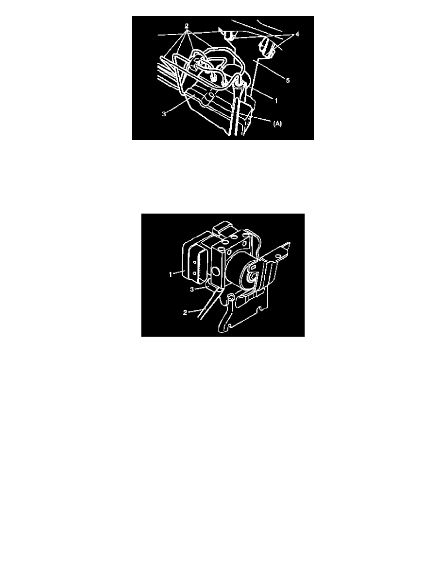
7. Remove bolt and pull out ABS (ESP) hydraulic unit / control module assembly (1) from bracket (3) using flat end rod or the like (2).
CAUTION:
^
Do not give an impact to hydraulic unit.
^
Use care not to allow dust to enter hydraulic unit.
^
Do not place hydraulic unit on its side or upside down. Handling it in inappropriate way will affect its original performance.
Installation
1. Install hydraulic unit / control module assembly by reversing removal procedure.
Tightening torque
Brake pipe flare nut for M10 a: 16 Nm (1.6 kg-m, 11.5 ft. lbs.)
Brake pipe flare nut for M12 b: 19 Nm (1.9 kg-m, 14.0 ft. lbs.)
ABS (ESP) hydraulic unit / control module assembly bolt c: 9 Nm (0.9 kg-m, 6.5 ft. lbs.)
ABS (ESP) hydraulic unit / control module assembly bracket bolt d: 25 Nm (2.5 kg-m, 18.0 ft. lbs.)
ABS (ESP) hydraulic unit / control module assembly bracket nut e: 25 Nm (2.5 kg-m, 18.0 ft. lbs.)