
Grand Vitara 4WD L4-2.4L (2009)
Diagnosis Procedure
NOTE: Before executing items in this flow, be sure to perform CAN Communication System Check. See: Initial Inspection and Diagnostic Overview
When "Lost Communication" is detected in any control modules, perform inspection using the following procedure.
1. Turn ignition switch to OFF position.
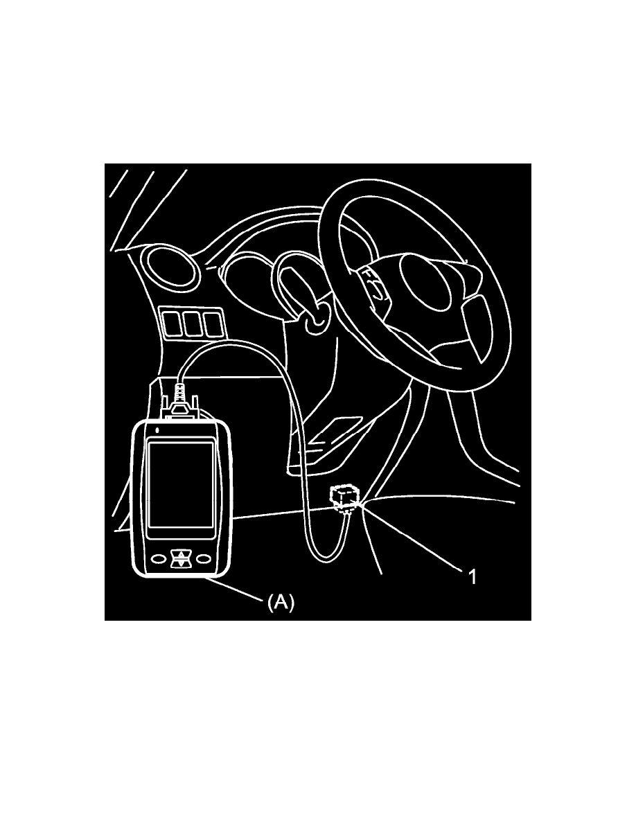
2. Connect SUZUKI scan tool to DLC (1) and ignition switch to ON.
Special Tool
(A): SUZUKI scan tool (SUZUKI-SDT)
3. Using "Communication Bus Check" under "Bus Check" of SUZUKI scan tool (SUZUKI-SDT), check for control module disabled to
communicate (no display on screen).
4. Based on above check results, select applicable diagnosis flow code (A to L) from Diagnosis Flow Selection Table and perform troubleshooting
according to selected diagnosis flow.
NOTE: If it is not possible to select suitable diagnosis flow code from "Diagnosis Flow Selection Table" or "two or more diagnosis flow codes
are selectable", perform Troubleshooting for Communication Bus Off. See: Troubleshooting For Communication Bus OFF
Diagnosis Flow Selection Table
NOTE: Diagnosis flow codes A to K link with CAN communication lines [a] to [k] of CAN Communication System Circuit Diagram.