
Grand Vitara JLS Plus 2WD V6-2.5L (2000)
5.
Remove the two 12 mm hex head bolts attaching the upper portion of the steering column to the column support and allow the column to be
lowered.
6.
Remove the phillips head screw attaching the transmission park lock cable housing to the arm on the ignition switch lock cylinder housing.
7.
Disconnect the transmission park lock cable from the white plastic AT lever located on the ignition switch lock cylinder arm. Do NOT remove the
white plastic AT lever from the arm at this time.
8.
Using a hammer and a small punch or chisel, place a notch in the head of the two bolts located on the top of the ignition switch lock cylinder
attaching plate. Continue using the hammer and punch/chisel to walk each bolt loose and remove. Discard the two bolts after removing.
NOTE:
The two bolts referred to in the above step do not have features that allow for the use of standard type tools when removing. To remove these
two bolts, create a notch or indentation near the outer edge of the head using a hammer and a small punch or chisel. Once the notch has been
created, continue using the hammer and punch/chisel in the notch to walk the head of the bolt around counterclockwise. Once the bolts have
broken loose, they can be removed with your fingers.
9.
Remove the three phillips head screws that attach the ignition switch lock cylinder housing to the turn signal switch assembly. To access the three
screws, rotate the steering wheel as required.
10.
Remove the ignition switch lock cylinder from the vehicle.
11.
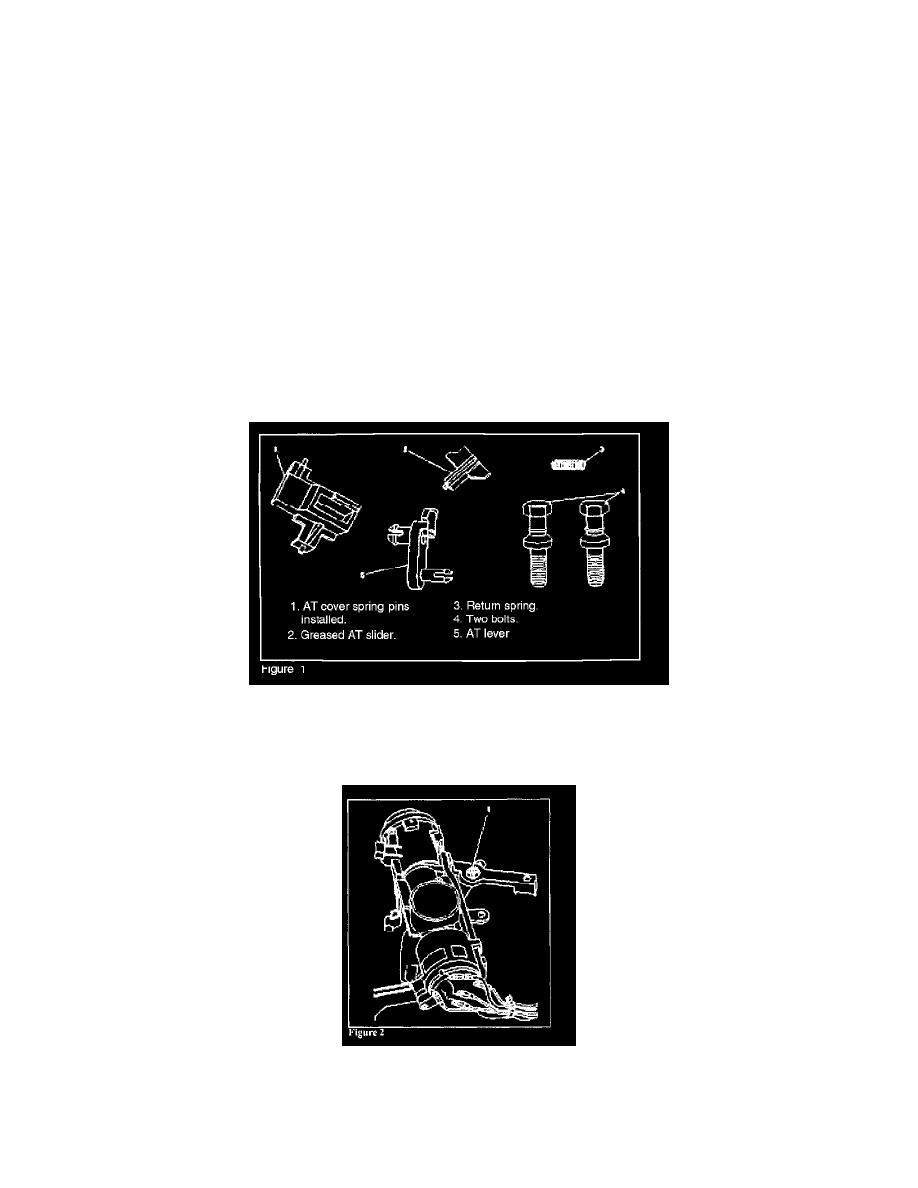
Review the contents of the parts contained in the kit (Figure 1).
NOTE:
DO NOT open smaller bag that contains the greased AT slider until instructed.
12.
With the ignition switch lock cylinder on a suitable work surface, review how the AT lever is attached to the lock cylinder assembly and then
remove it by squeezing the four retaining tabs (1) together (Figure 2).
NOTE:
Reviewing how the AT lever is installed on the lock cylinder assembly prior to removal in the above step will make installation easier later in