
Sidekick L4-1324cc 1.3L SOHC 5 Carb 8V (1989)
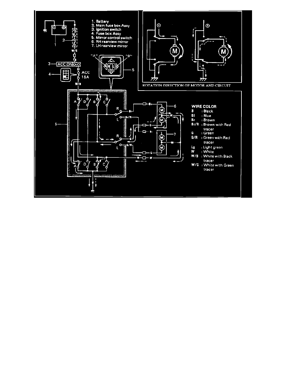
ELECTRIC POWER MIRROR CONTROL SYSTEM CIRCUIT The figure below shows the electric power mirror control system circuit. Marks A, B,
C and D in the figure represent how that the circuit operates when the corresponding button A to D of the mirror control switch is pressed. The solid
arrow line ( ) shows the circuit used when the selector switch is set to "R" and "A" is pressed. The broken arrow line ( ) shows that when "B" is pressed.
The rotation direction of the motor is controlled by the direction of the electric current flowing to the motor. The insert shows the circuits formed when
the motor runs clockwise and counterclockwise respectively.