
Sidekick 2WD L4-1590cc 1.6L SOHC 0 TBI 8V (1992)
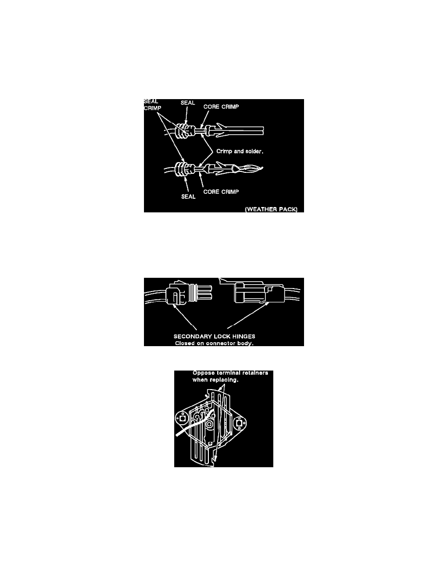
a.
Slip cable seal away from terminal (if seal exist).
b.
Cut wire as close to terminal as possible.
c.
Slip a new cable seal onto wire (if necessary).
d.
Strip 5 mm (3/16") of insulation from wire.
e.
Crimp a new terminal to the wire.
f.
Solder with rosin core solder.
g.
Slide cable seal toward terminal (if equipped with seal).
h.
Crimp cable seal and insulation (if equipped with seal).
i.
Apply grease to connectors outside passenger compartment where connector was originally equipped with grease.
Figure 17
To re-use a terminal or lead assembly, see previous steps c through i for repairs. Be sure to keep cable seal (if equipped) on terminal side of splice.
5.
Insert lead from the back until it catches.
6.
Install TPA's, CPA's and/or secondary locks, if equipped (see Figures 18 & 19).
Figure 18
Figure 19
Pull-to-Seat Connectors
NOTE: The following general repair procedures can be used to repair most types of connectors. Use the Pick(s) or Tools that apply to your terminal.
Use Terminal repair kit J 38125 or equivalent.