
Sidekick 4WD L4-1590cc 1.6L SOHC 0 TBI 8V (1990)
Valve Spring: Service and Repair
16 Valve Engines
Disassembly
1.
Remove cylinder head assembly as described under CYLINDER HEAD, then the distributor gear case, intake manifold with throttle body and
exhaust manifold from cylinder head.
2.
Remove rocker arms, rocker arm shaft and camshaft as described under ROCKER ARMS, ROCKER ARM SHAFT & CAMSHAFT.
3.
Compress valve springs using valve lifter 09916-14510 and valve lifter attachment 09916-14910 or their equivalents, then remove valve cotters
using forceps 09916-84510 or equivalent.
4.
Remove valve lifter and valve lifter attachment, then spring retainers and valve springs.
5.
Remove valves from cylinder head. Prior to removing valves from head, ensure there are no burrs on valve stems.
6.
Remove valve stem oil seals from valve guides, then the spring seats.
7.
Drive valve guides out from combustion chamber side to valve spring side using valve guide remover 09916-44910 or equivalent.
8.
Place disassembled components in order so they can be installed in their original positions. Do not re-use valve stem seals or valve guides.
9.
Inspect all components for wear, burn, distortion and proper clearances, replacing as necessary.
Assembly
1.
Ream valve guide bores using 11 mm reamer 09916-38210 and reamer handle 09916-34541 or their equivalents to remove burrs and true bores.
2.
Heat cylinder head uniformly to a temperature of 176-212°F so head will not be distorted, then drive new valve guides into bores using valve
guide installer handle 09916-58210 and valve guide installer attachment 09916-56011 or their equivalents. Drive valve guides in until valve guide
installer contacts cylinder head. After installation, ensure guides protrude by .045 inch from cylinder head.
3.
Ream valve guides using 5.5 mm reamer 09916-34550 and reamer handle 09916-34541 or their equivalents, then install valve seats to cylinder
head.
4.
Apply engine oil to new stem seals and spindle of valve stem seal installer 09917-98221 or equivalent, fit oil seal to spindle, then install seals to
valve guides by hand, using valve guide installer handle 09916-58210 or equivalent.
5.
Apply engine oil to valve stem seals, valve stems and valve guides, then install valves into guides.
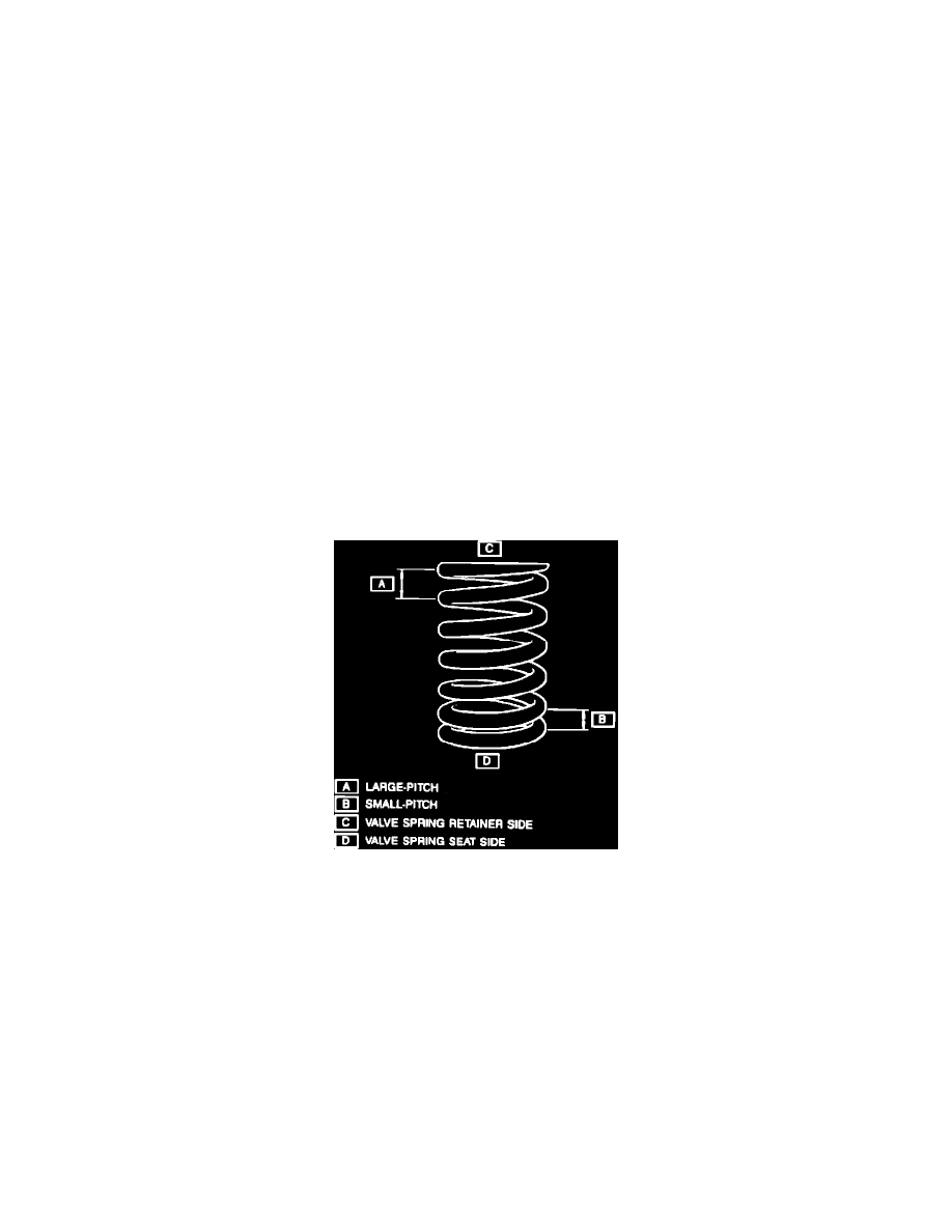
Fig. 27 Valve Spring Installation
6.
Install valve springs and spring retainers, as shown in Fig. 27.
7.
Compress valve springs using valve lifter 09916-14510 and valve lifter attachment 09916-14910 or their equivalents, then fit two valve cotters
into groove in valve stems using forceps 09916-84510 or equivalent.
8.
Install rocker arms, rocker arm shaft and camshaft as described under ROCKER ARMS, ROCKER ARM SHAFT & CAMSHAFT.
9.
Install distributor gear case, intake manifold with throttle body and exhaust manifold to cylinder head, then the cylinder head assembly as
described under CYLINDER HEAD.