
Sidekick 4WD L4-1590cc 1.6L SOHC 0 TBI 8V (1990)
Ignitor: Testing and Inspection
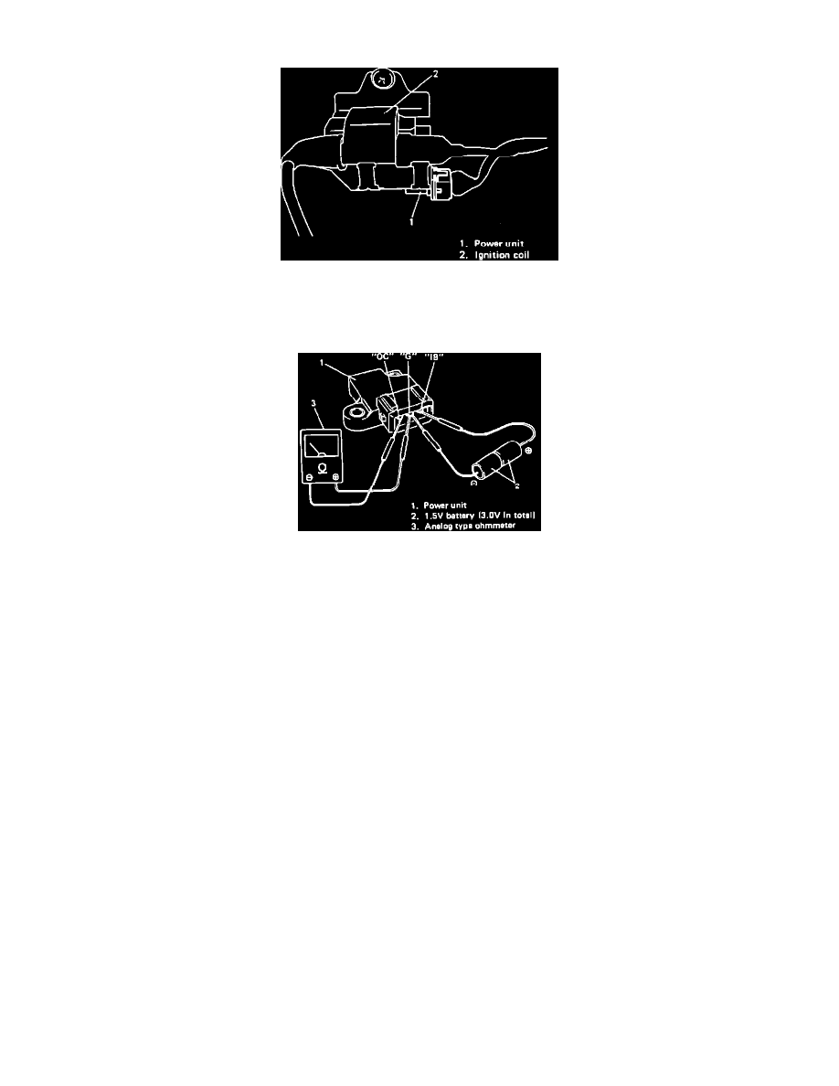
Fig. 17 Power Unit Location
1.
Remove power unit from ignition coil bracket, Fig. 17.
2.
Arrange two new 1.5 volt batteries in series.
Fig. 18 Checking Power Unit
3.
Connect positive terminal of ohmmeter to G terminal of power unit and negative terminal to OC terminal, Fig. 18.
4.
Check for continuity when batteries are connected to G and IB terminals, Fig. 18. Continuity should not be present when batteries are not
connected.
5.
If test is not satisfactory, replace power unit.