
SX4 2WD L4-2.0L (2007)
If measure voltage is out of specification or does not vary linearly as the shown in graph, check related wire circuit and HVAC control module. If
wire circuits and HVAC control module are OK, go to next step.
Air flow control actuator output voltage
0.48 - 4.53 V (linear variation as given graph)
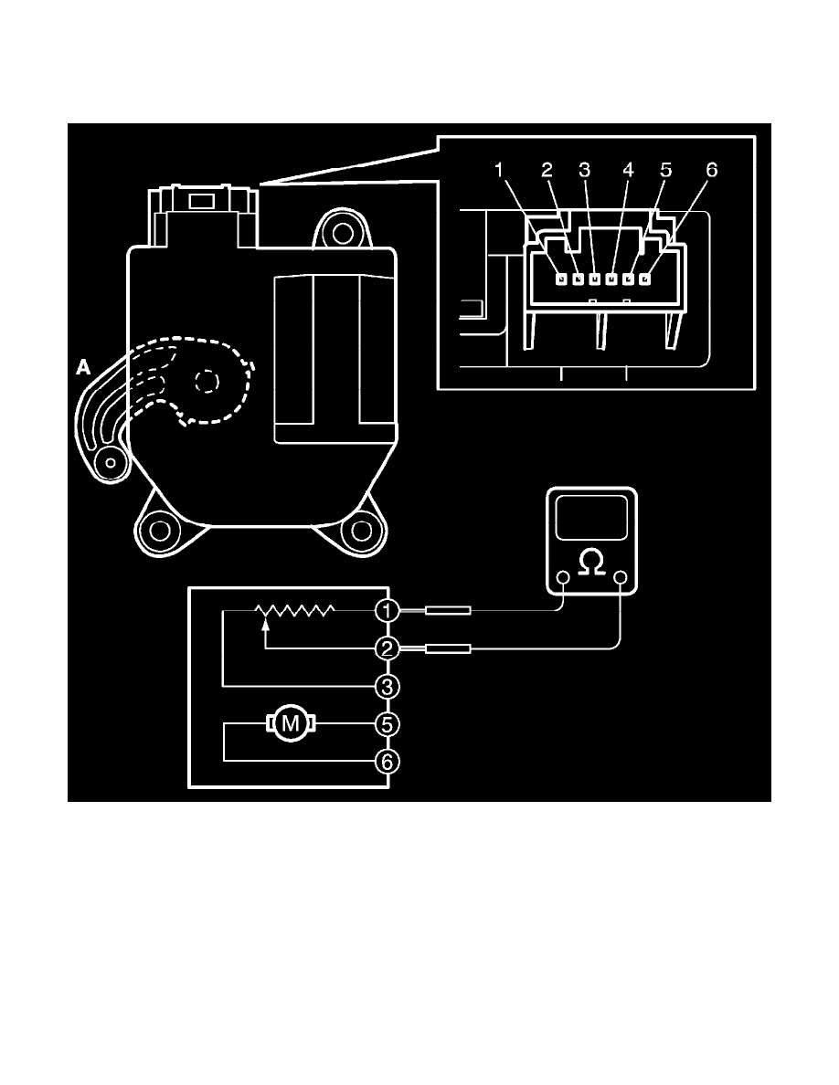
7. Set air flow selector of HVAC control module to "DEF" position with ignition switch turned ON, and make sure if the position of actuator lever is
"DEF" position (A).
8. Turn ignition switch to OFF position, and then disconnect connector from air flow control actuator.
9. Measure resistance between terminal "1" and "2".
Air flow control actuator resistance between terminal "1" and "2" (DEF position)
(Reference value)
Approx. 0.45 kohms at 25 °C (77 °F)