
XL-7 2WD V6-3.6L (2007)
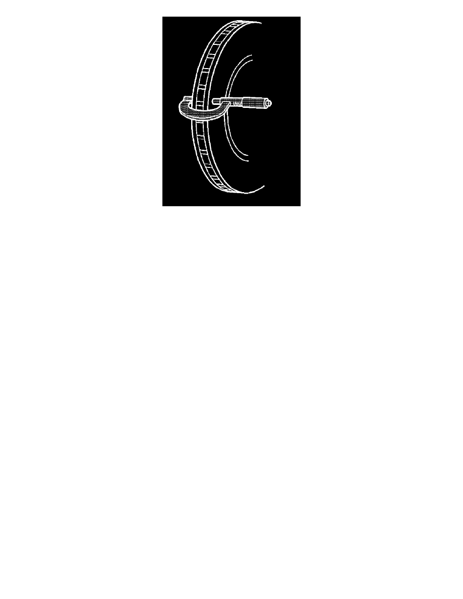
3. Using a micrometer calibrated in thousandths-of-a-millimeter, or ten-thousandths-of-an-inch, measure and record the thickness of the brake rotor at
four or more points, evenly spaced around the rotor. Ensure that the measurements are only taken within the friction surfaces and that the
micrometer is positioned the same distance from the outer edge of the rotor, about 13 mm (0.5 in), for each measurement.
4. Calculate the difference between the highest and lowest thickness measurements recorded to obtain the amount of thickness variation.
5. Compare the thickness variation measurement to the following specification:
Specification
Brake rotor maximum allowable thickness variation: 0.025 mm (0.001 in)
NOTE: Whenever a brake rotor is refinished or replaced, the assembled lateral runout (LRO) of the rotor must be measured to ensure optimum
performance of the disc brakes.
6. If the brake rotor thickness variation measurement exceeds the specification, the rotor requires refinishing or replacement.
Brake Rotor Assembled Lateral Runout Measurement
Brake Rotor Assembled Lateral Runout Measurement
Special Tool
^
J 39544-KIT Torque-Limiting Socket Set, or equivalent
^
J 41013 Rotor Resurfacing Kit
^
J 42450-A Wheel Hub Resurfacing Kit
^
J 45101 Hub and Wheel Runout Gage
^
J 45101-100 Conical Brake Rotor Washers
WARNING: Refer to [Brake Dust Caution]Brake Dust Caution.
NOTE:
^
Brake rotor assembled lateral runout (LRO) exceeding the maximum allowable specification can cause thickness variation to develop in the brake
rotor over time, usually between 4,800-11,300 km (3,000-7,000 mi).
^
Brake rotor thickness variation MUST be checked BEFORE checking for assembled lateral runout (LRO). Thickness variation exceeding the
maximum acceptable level can cause brake pulsation.
1. Matchmark the position of the brake rotor to the wheel studs if this has not been done already.
NOTE: Whenever the brake rotor has been separated from the hub/axle flange, any rust or contaminants should be cleaned from the hub/axle
flange and the brake rotor mating surfaces. Failure to do this may result in excessive assembled lateral runout (LRO) of the brake rotor, which
could lead to brake pulsation.
2. Inspect the mating surface of the hub/axle flange and the brake rotor to ensure that there are no foreign particles, corrosion, rust, or debris
remaining. If the wheel hub/axle flange and/or if the brake rotor mating surfaces exhibit these conditions, perform the following steps:
a. Remove the brake rotor from the vehicle.
b. Using the J 42450-A, thoroughly clean any rust or corrosion from the mating surface of the hub/axle flange.
c. Using the J 41013, thoroughly clean any rust or corrosion from the mating surface of the brake rotor.